The bare minimum needed to produce a 360-degree film is the same as regular filmmaking. A video camera, a suitable lens, and a means to store the footage. But to shoot with one lens means to make compromises, as this section will discuss.
The most important guidelines for Capturing 360 are:
–A Stable Rig that is as small as possible, to minimise parallax.
–Identical cameras, with identical settings for each camera.
Today we are spoilt for choice when it comes to camera selection with the advent of very high resolution consumer cameras. They often come with some caveats but as is becoming apparent, shooting VR is all about compromise. Some might have astounding resolution but horrendous colour, others might give you complete control over exposure and synchronization but are the size of small refrigerators.
Finding the sweet spot that will suit your needs requires an understanding of what implication each decision will have. The first half of this chapter deals with the technical aspects of Camera selection, whilst the second half addresses the rig and planning.
For those not interested in the technical aspects of camera selection and want to get to the meat of the chapter, grab the widest lens you have and head straight to RIGGING.
Quick Navigation
- Camera Size
- Sensor size
- Camera Resolution
- Frame Rate
- Dynamic Range and compression
- Lens choices
- Rigging
- All-in-one systems
- Shooting for Synchronisation
- Single Camera Workflow
- Further Reading
Camera Size.
Camera size has the most direct correlation to parallax and as will play the largest role in how well your footage will fare during stitching. Using small cameras allows them to be placed very close together, and in other words, as close as possible to the no-parallax point. Although any offset from this point will cause errors to appear, smaller is definitely better. As an example, the GoPro Hero4 has an astoundingly small body, making it very favorable for multi-camera setups. Using 6 cameras, the rig is scarcely larger than two balled up fists.
Larger cameras generally are generally larger for a reason though, packed with larger sensors and more sophisticated electronics. Compared to the Gopro, a DSLR seems ridiculously large – but they offer interchangeable lenses, better low light performance, manual exposure and remote recording. Parallax errors aplenty though.
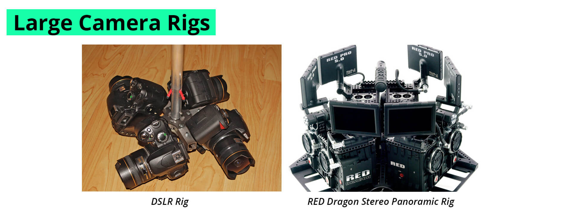
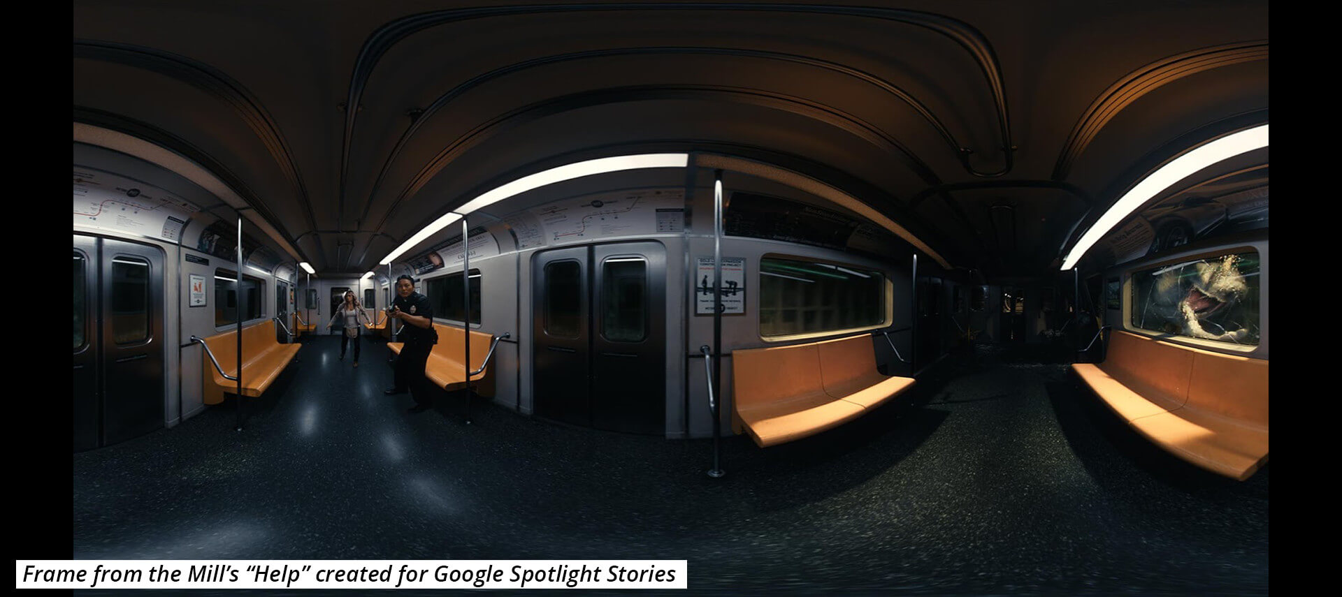
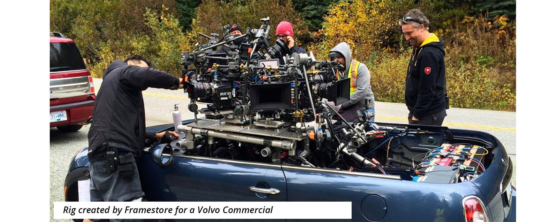
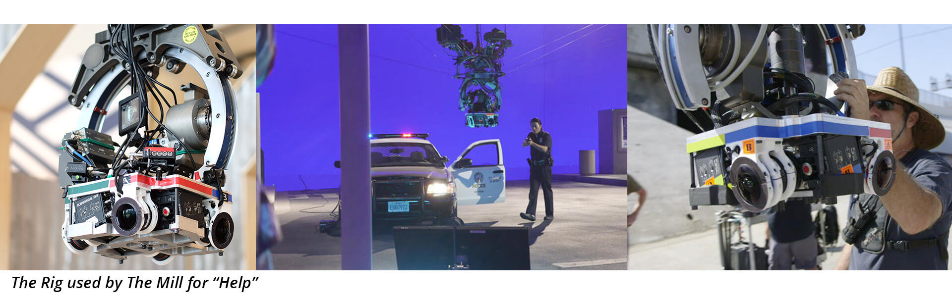
Professional cinema quality cameras like the Arri Alexa and Red Dragon are truly hefty and cannot be swung around as easily. But with all that bulk comes all the features of a DSLR as well as true time synchronisation, uncompressed recording and a dynamic range that puts any consumer camera to shame. The RED cinema cameras are the current front runners for many VR productions and the recently completed “Help” by the Mill, created for the Google Stories App was shot using such a rig.
Sensor size
Generally when discussing sensor size, the number one consideration is the effect it has on depth of field. Large sensor being capable of incredibly shallow depth of field. But as the focal length decreases and the lenses start getting wider, this effect becomes trivial. There is virtually no depth of field on a Fisheye lens and since it is more than likely that a wide lens will be used for VR, the question becomes – What use is a large sensor?
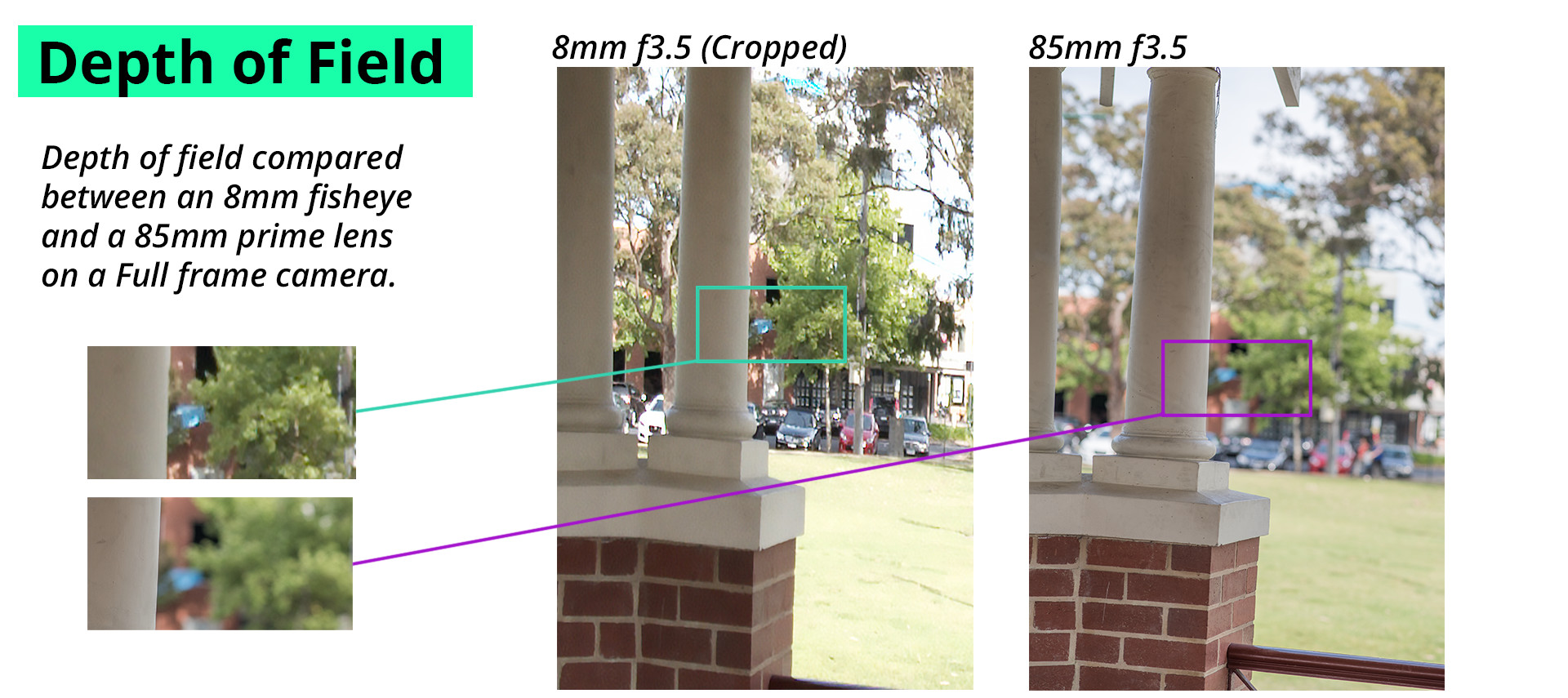
Large sensors have larger surface areas, and that translates to an increased ability to catch photons. Small sensor cameras have very poor low-light performance when compared to Full-frame cameras. The Sony a7s for example, can comfortably capture clean imagery in low-light, or even none at all.
For cameras with smaller sensors, such as the GoPro, their miniscule sensors mean that they have almost no depth of field to start with, which is good. Unfortunately it also means that they have a harder time gathering enough light to make a picture and generally perform better in daylight.
Sensor sizes also directly influences field of view, as will be seen in the section on lens choices. Large sensors can “see” more of the picture that a lens makes, and often there is a lot of information that the lens can capture that gets lost because of small sensors. Most of the time the area lost is not sharply focussed, or heavily vignetted, other times though, as with some fisheye lenses, that information may very well be very useful in panoramic video.
Camera Resolution
Panoramas are usually very high resolution, simply because of the fact that the are combination images. Just how high is a matter of the cameras doing the capturing. If there is a delivery requirement for the resolution of the project, this is where that should be addressed.
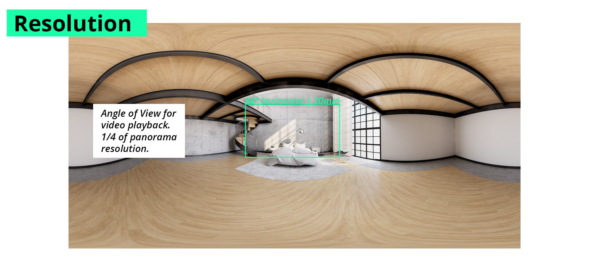
Panoramic videos can be created at any resolution, but just because it is possible to shoot and deliver in UltraHD or 8K, doesn’t mean your audience would be able to view it as many mobile phones and computers cannot smoothly play such large files. Because the final view will be a small window into the panorama, there is a need to ensure that there is enough resolution to still have detail once delivered.
There is no currently standard for what resolution a VR-Video should be, and it is unlikely that that will change because of the myriad of ways to distribute. There are guidelines however, and many of them seek to ensure that the video uses as much of the available resolution on the distribution platform as possible. The resolutions of a number of platforms for VR are discussed in Chapter 5.
GoPro cameras punch well above their weight when it comes to resolution, and even the lowest available setting suitable for 360-video (1440p) results in a final panorama in excess of 5000 pixels wide.
For interchangeable lens cameras like DSLR’s and canons, the resolution can be tuned a bit by using different lenses and more of less cameras. Though using more than 4 can start to create some unwieldy rigs. Four full frame Canon cameras with 180º fisheye lenses will yield a panorama of around 3200 pixels wide. By changing lenses and adding cameras, that number can be increased as needed at the cost of increased parallax errors.
Frame rate
Frame rate in Virtual Reality aims to out-pace the human brain’s ability to process information. If a picture can be updated faster than the brain can spot the differences, there is a greater chance that viewers will feel immersed. The current industry standard is to maintain a frame-rate of 75 frames per second.
This can be taken to mean that – the video needs to play at 75 frames per second, which would be very hard indeed to create and manage. Or it may be taken to mean that the video player, the application that updates the viewers field of view, needs to update at least 75 times per second – leaving the video to play at any frame rate that convenient to the story.
In tests done during the production of this website, it was found that very high frame rate video often has little discernible benefit. Some fast moving action, especially horizontal, does however benefit but on the whole the reduced processing overhead of having fewer frames to work with far outweighed the gains. Beyond the barely tangible effect of reduced motion blur, most people could not spot the difference between 50fps and 25fps video. If the app had even minor delays delays however, it was instantly noticed.
This in fact frees filmmakers to explore any number of new techniques without such a restriction enforced upon them. And allowing us to use the frame rates we are accustomed to working – and using them as the powerful story telling tool they are.
With that said, capturing in higher-frame rate capture does have a benefit with regards to synchronisation. By recording the scene in finer slices of time – so to speak. After capture, the frame rate can be reduced for presentation.
Dynamic range and compression
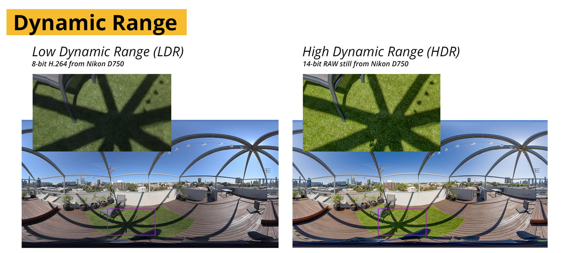
Dynamic range refers to the greatest difference the camera can record between the brightest area in a scene, without clipping any detail, and the darkest, again, whilst still maintaining detail.
Dynamic range plays an important role in the capture of 360-video because of the fact that many likely outdoor situations will have incredibly large differences in brightness. For a traditional production it may be possible to dress the set in such a way as to reduce the intensity of bright light sources for example, or bounce light onto dark areas to balance them out. Such techniques are hard to recreate with 360 films as both the light sources, as well as the light modifiers (cards, scrims, reflectors) would be visible in the frame unless well hidden – so well that usually they can’t do the job they were intended for.
The dynamic range of the camera also dictates how much post colour correction and grading can be done to a piece of footage. Creative grades often push the colour values quite substantially and should there be underlying clipping or heavy compression in the originals– these will often be made visible.
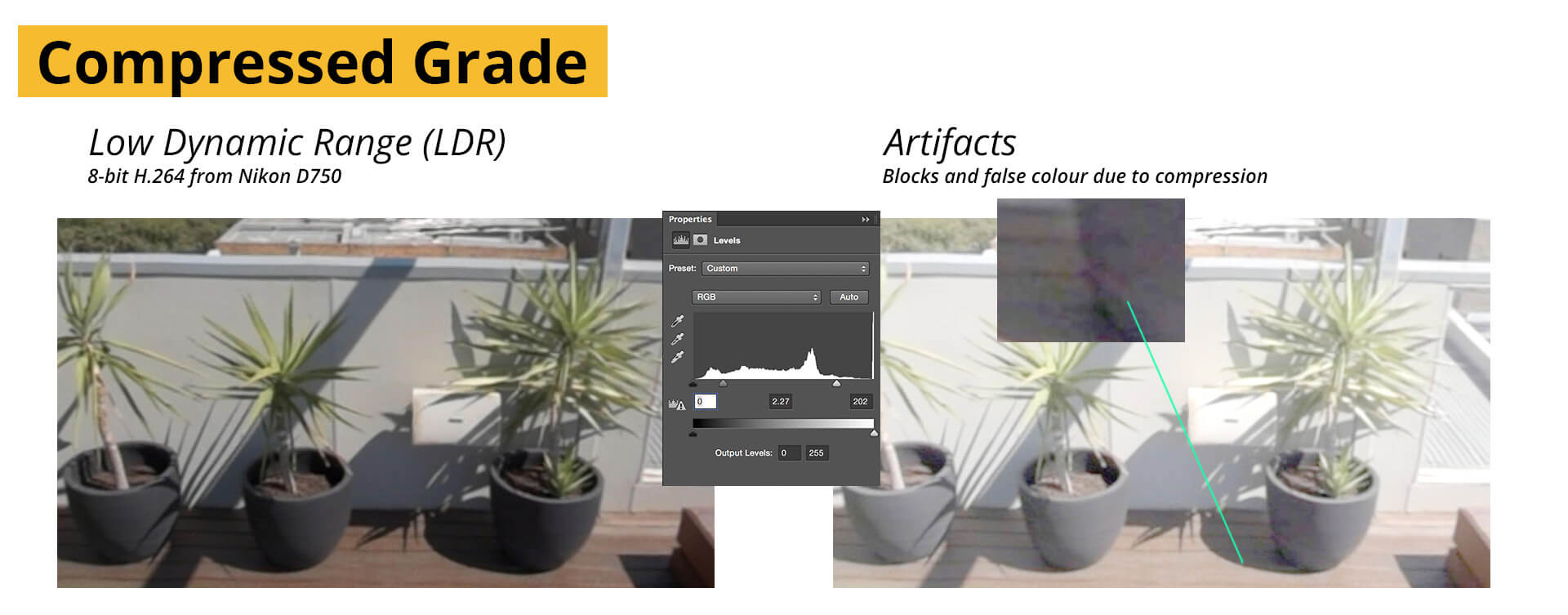
For most cameras available to amateur filmmakers, the built-in compression leaves a lot to be desired. Even the most incredible sensors, like those in DSLR’s are crippled by the lack of built-in quality codecs.
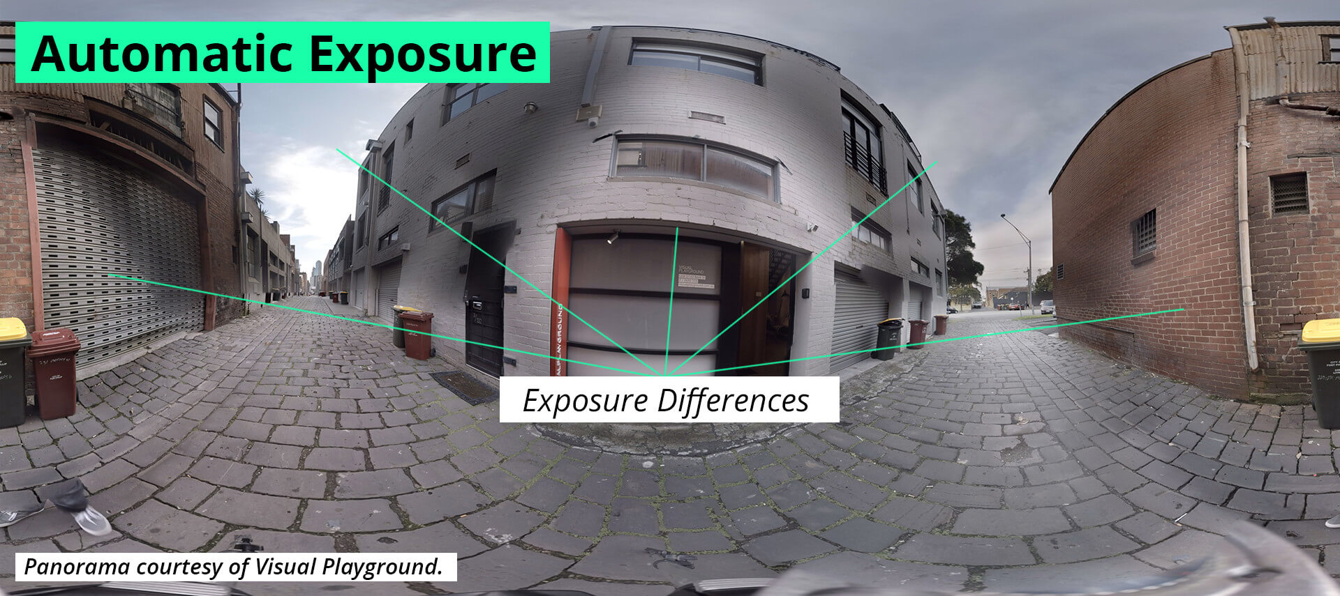
When dealing with a limited dynamic range, exposure selection becomes critical, but with some cameras, such as the GoPro, there is no option to select exposure manually. For multiple cameras, this leads to each camera adjusting their exposure based on which part of the scene they may be facing. One might be facing a dark corner and life exposure, whilst another might be in view of the sun and severely reduce the exposure. Once they are stitched, these images will have greatly varying light levels and will need to be re-aligned using colour correction software. If the difference is greater than the dynamic range of the cameras, some of the details in the scene could be beyond recovery. Know your camera.
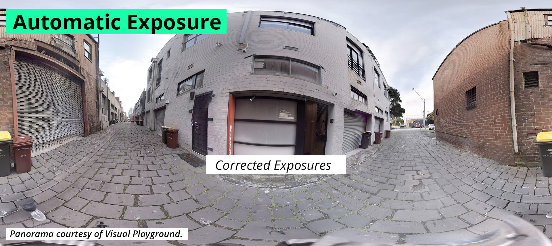
For situations where the exposures varies mildly – typically within a stop or two, this is generally less of a concern and can be corrected for during the stitching process as will be discussed in Chapter 4.
For DSLR’s like the Canon or even Nikon cameras, the codecs are scarcely better, although they do have the ability to set the exposure and white balance on each of the cameras manually. Though it is still likely that a camera may over-expose a shot during filming, it is no longer up to chance and is completely controllable by the cinematographer.
Higher-end cameras such as the Blackmagic range, Red cinema cameras and the Arri Alexa Mini cameras all have a distinctly greater dynamic range which can handle scenes with far more fidelity than consumer cameras. It is important to note that the Sony a7s, albeit a consumer grade camera, has a logarithmic codec available (s-log2) which when used correctly could enable it to capture scenes that would be beyond the scope of any of the other DSLRs or GoPros.
Lens choices
Lenses, are still lenses. They’ll define the quality of your footage, the sharpness and detail in your panorama, and how your shoot will fare in low light. But alongside these usual suspects, your lens will also dictate how many cameras your rig will need to have, and how it will be built.
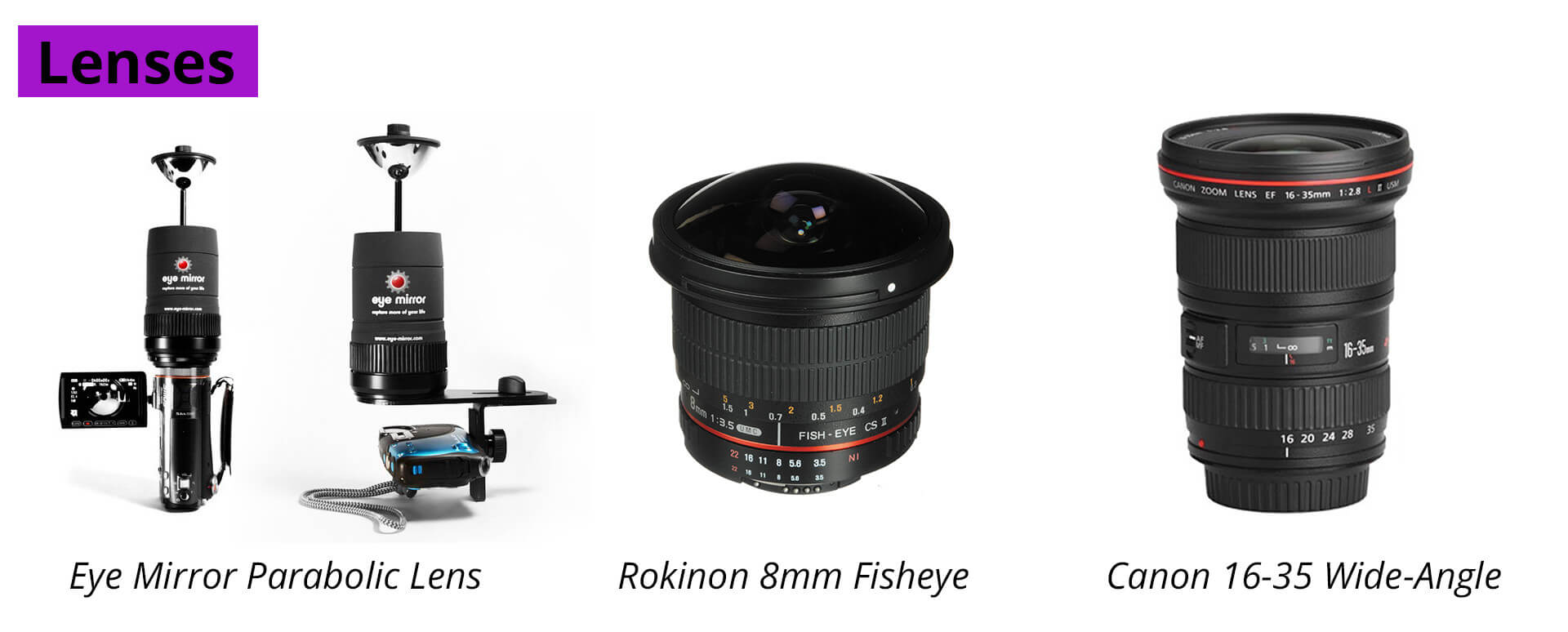
The widest possible lenses for VR are parabolic lenses such as the eye360 and panopro. These are not lenses as much as lens extentions, complicated mirrors that slot over and in front of a normal lens. The mirrors capture a wider field of view, much wider, the full 360 degrees around the camera. Parabolic lenses may seem attractive to shoot with as they offer a way to capture without seams, but they have some drawbacks. Firstly, they don’t cover the areas above and below, so extra cameras would be needed. Secondly, squeezing all of that information onto one sensor also means you’ll need a very high resolution sensor to capture it all. Lastly, the mirrors need to be kept perfectly scratch and dirt free as even the smallest smudge or crack will show up.
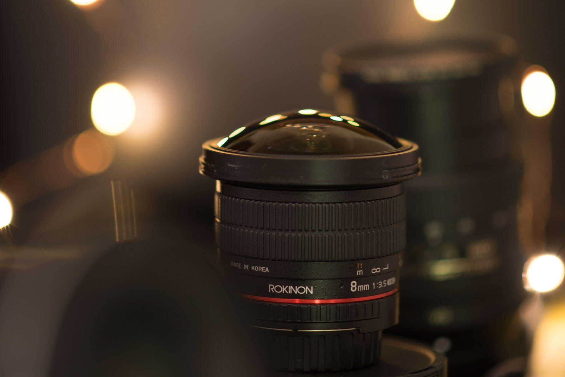
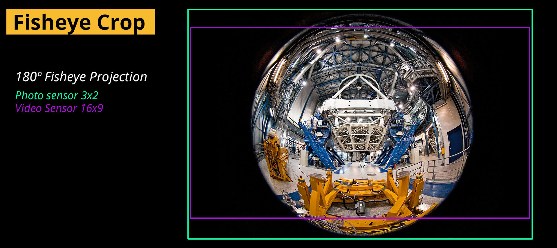
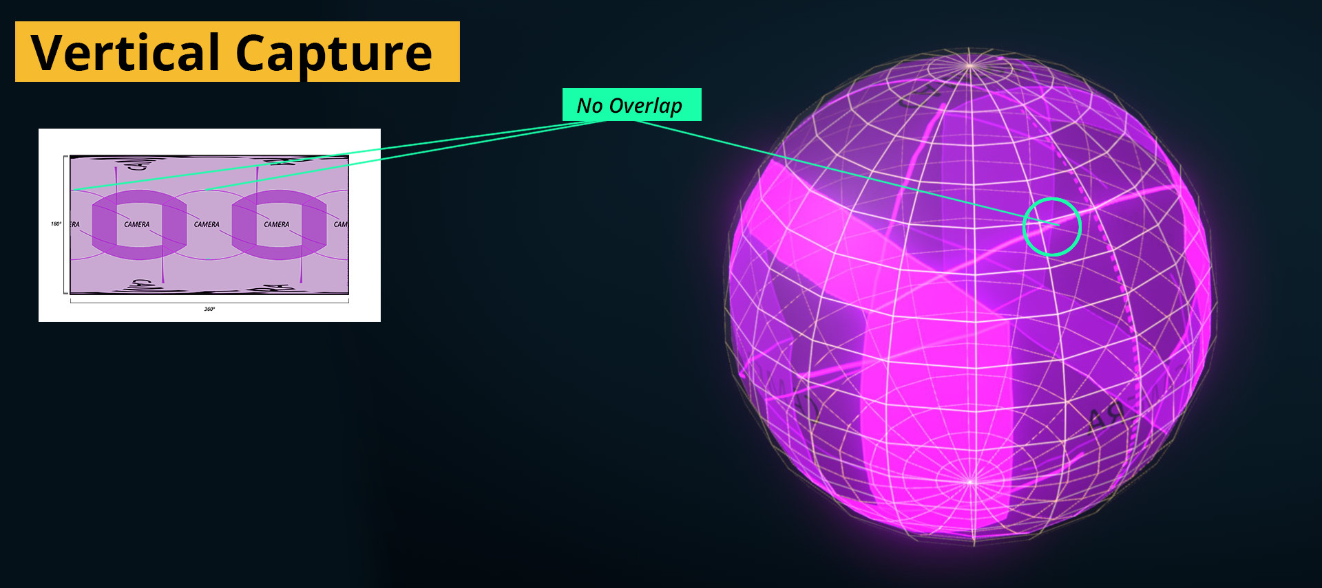
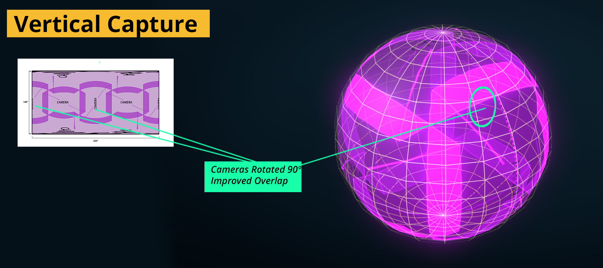
Most VR rigs will aim to use as wide a lens as possible, and there is no wider than a spherical Fisheye. Depending on the lens, these can capture up to, and sometimes more than, 180 degrees. They do this with a bulged glass element at the front that collects light from all around it, and focusing it as a circular image on the sensor. Sensors, however aren’t round, and the area not covered by the lens will be wasted resolution. These lenses were also originally designed for a taking photos, meaning that the circular image they make, was designed to fit inside a sensor with 3:2 ratio of width to height. When shooting video, most cameras crop their sensor’s ratio down to 16:9, to match the ratio of HD Video. So what would have been a full 180 degree view for a photo becomes a less so on video.
Dependent on the lens used, this might remove between 10 and 25% lost. But these are still very capable lenses offering incredibly wide views, and so to counteract the lost pixels, cameras with fisheye lenses are often rotated to shoot vertically. When doing so, the lens still captures a full 180 degrees of the vertical edge of the panorama, and as we’ll be using more than one to capture the horizontal side – there is still plenty of overlap to use.
Normal, or rectilinear lenses, offer diminishing value for VR as the focal length increases. It would be rare to see a rig that uses a normal lens to capture unless the body is incredibly small – think webcams. Circumstances where a normal lens may very well be useful is when a view from a normal lens may be stitched together with wides angle footage.
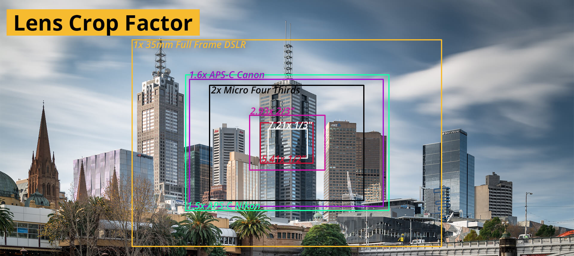
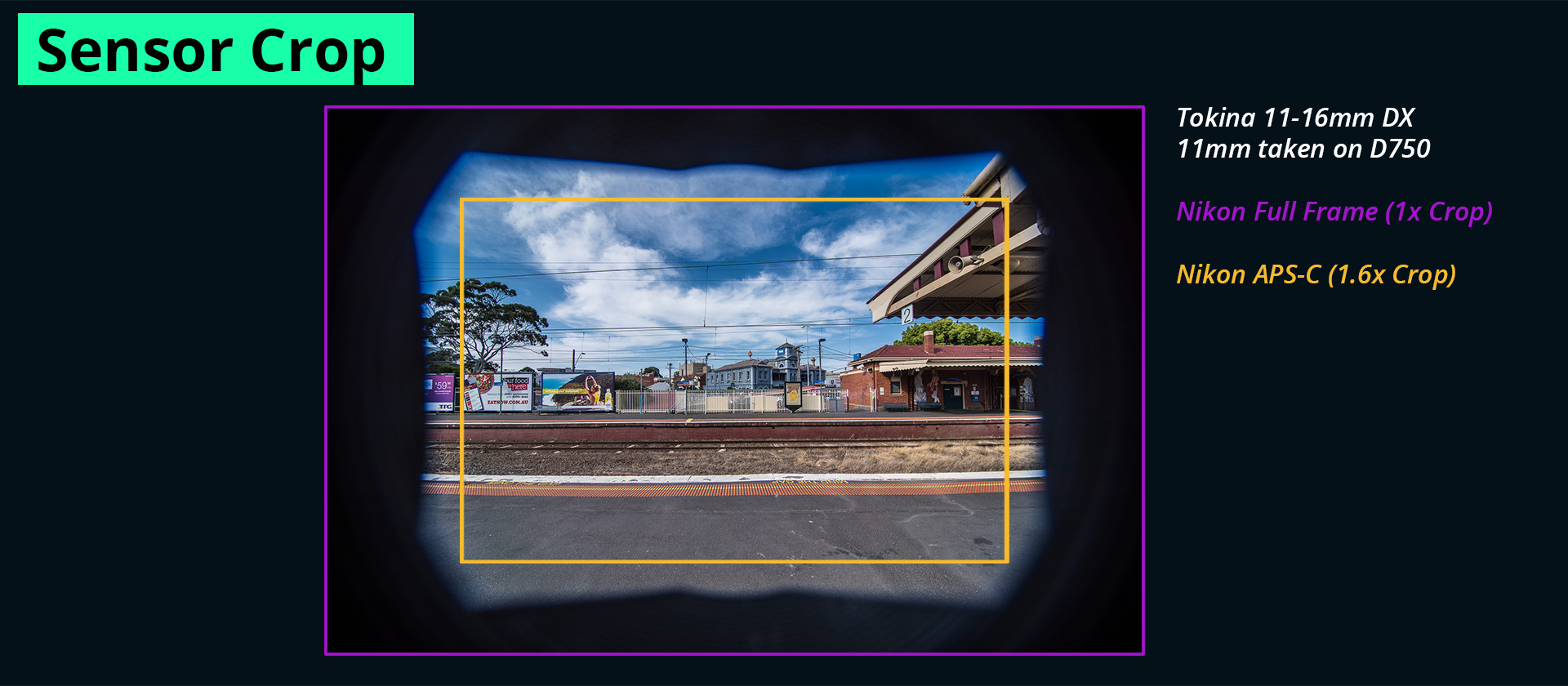
To find out what the field of view of your lens is, you’ll need to know the focal length of the lens and what camera it will be used on. Most often, the focal length is expressed as a measurement in millimeters e.g. 50mm. Focal lengths are standardised only so far as they apply to 35mm film cameras, or full frame Digital cameras. As the sensor sizes change, the difference in size generally appears as a “cropping” of the image. Because a smaller sensor cannot receive the whole image a lens makes, the amount that is lost is expressed as a “cropping factor” or a number above 1.
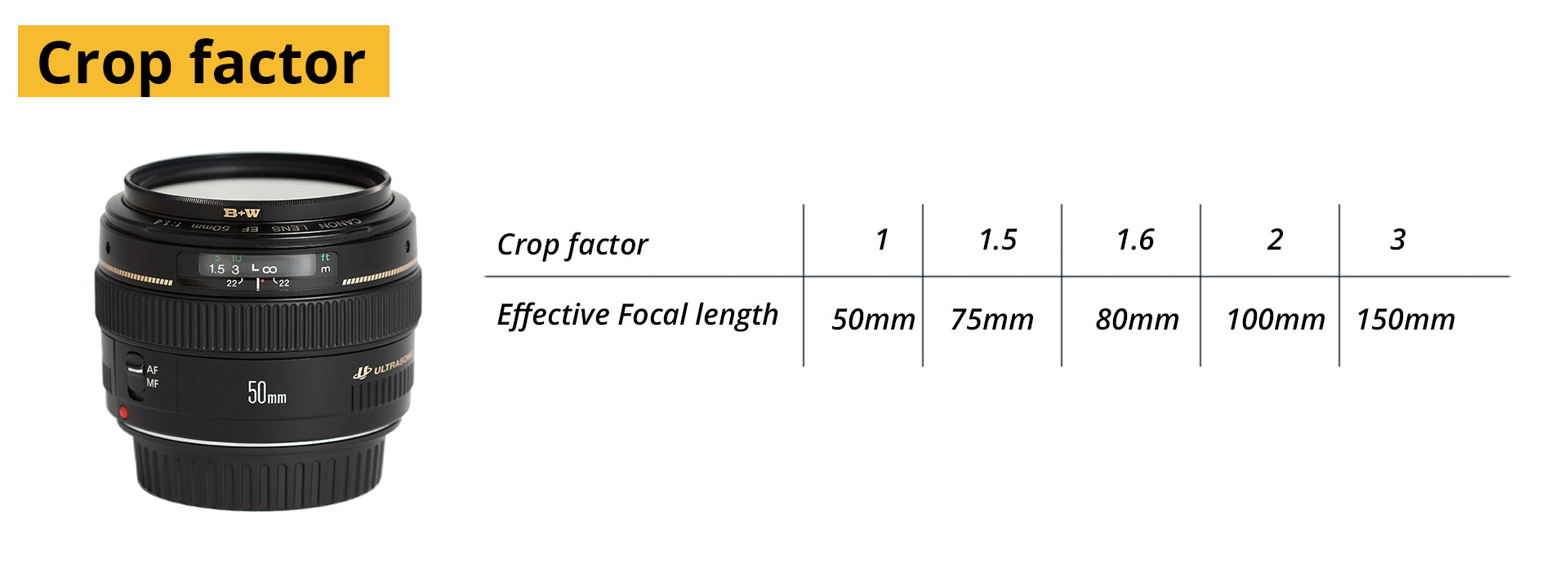
A full frame camera therefore has a crop factor of 1, in that it can use all the information from a lens. A Nikon crop frame sensor, like the D7000 has a crop factor of 1.5, meaning that it can only accomodate around 60 percent of the image as opposed to a full frame camera. What makes the crop factor very intuitive, is that the focal length can be multiplied by the crop factor to find the approximate focal length equivalent on that camera. A 50mm lens on a D7100 with a crop factor will have roughly the same field of view as a 75mm lens on a 35mm lens on a camera. (50 x 1.5). So, to calculate the field of view, we only need to remember one set of numbers, i.e. those of the 35mm cameras, and multiply them with the cameras we use to get the correct angles.
Sometimes rough isn’t good enough though, and to find out exactly what the field of view is you can use an online calculator to do the math for you. You will however need to know the sensor size, either in inches or centimetres along with the focal length of your camera.
To make the most of the lenses at your disposal might mean mounting the cameras at akward or unusual angles, and for that we’ll move on to rigging.
The rig
Arranging cameras in an array, or rig, is a simple concept but it takes some careful planning to make the most of the gear available. Especially when trying to get the highest quality capture, using as few cameras as possible, all the while keeping the needs of power, data management and rig weight satisfied.
As manufacturers catch up with demand, simple integrated camera systems will become available at any pricepoint, the same way as what has happened to traditional video cameras. In fact, a number of promising systems are already on the market, or soon to be – a list of some of them can be found at the end of the chapter.
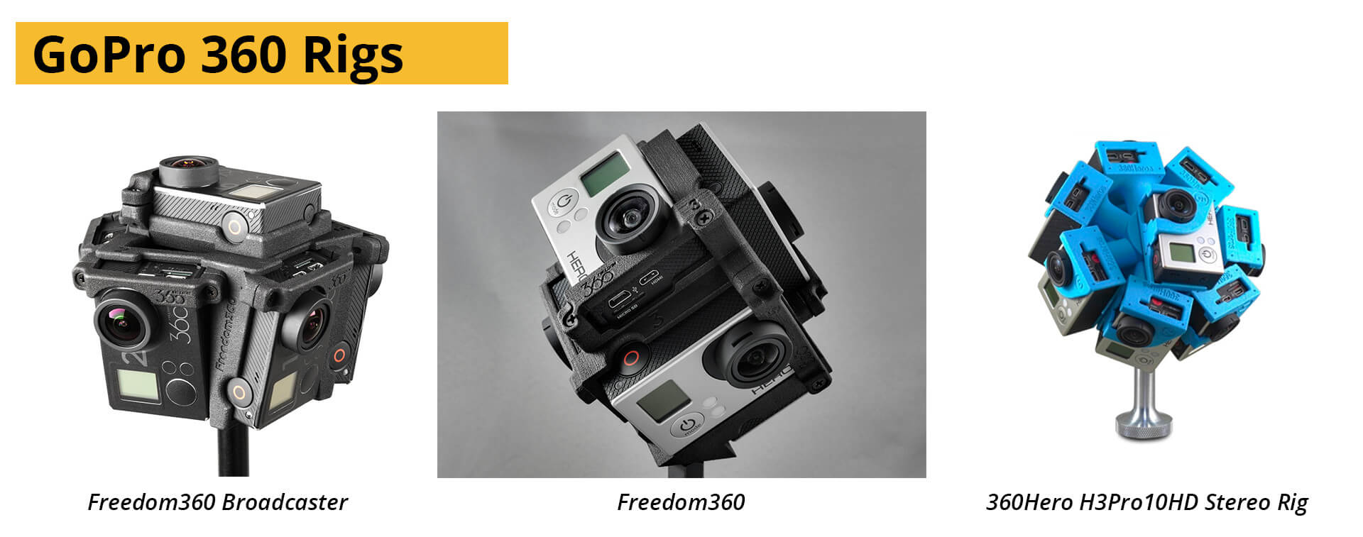
As for rigs, the empty frames to which you can attach cameras, there are a few available to buy, but as there are thousands of different camera shapes and sizes available, their usefulness is often extremely limited. One very notable exception are the Hero360 and Freedom360 rigs, made expressly for GoPro cameras. Much of their success can be attributed to the consistency in design between the gopro models, along with the relatively inexpensive nature of the individual cameras (compared to more advanced imaging equipment).
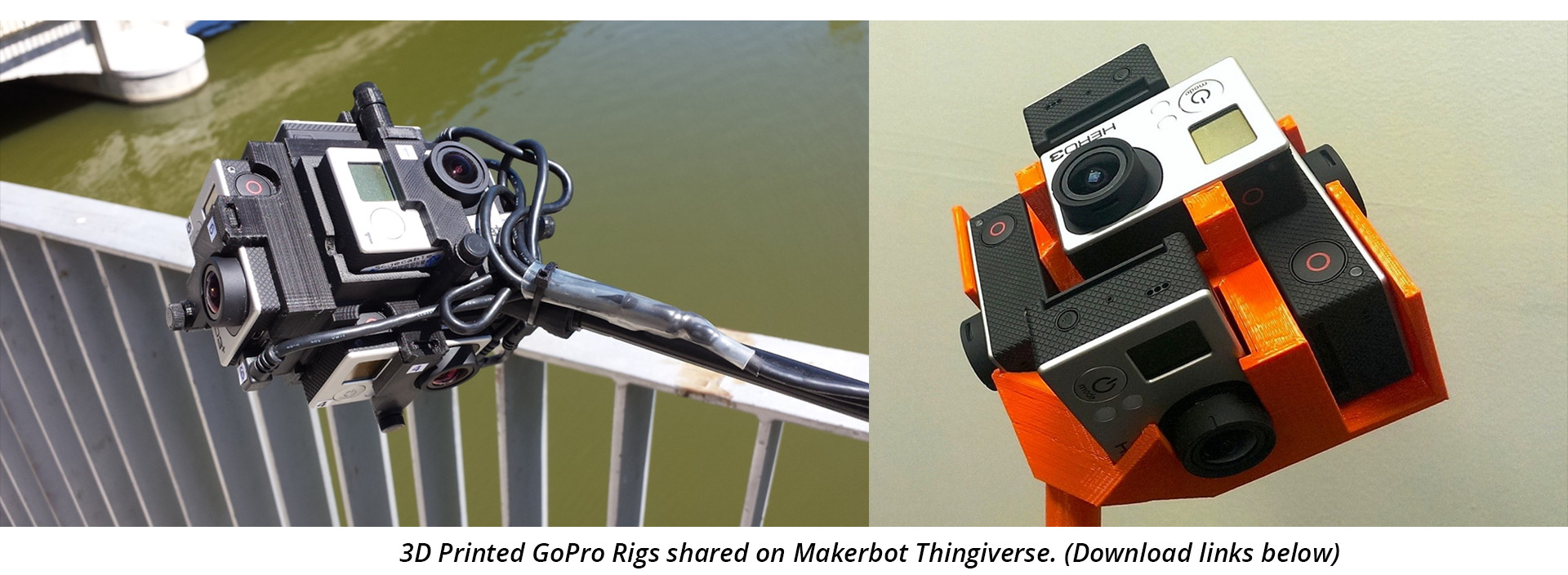
3D printable rigs for GoPro cameras are also available for free, shared by users on Makerbot’s Thingiverse website. Examples can be downloaded here and here.
The benefits of using a commercially established rig is that the orientation used for each camera along with their layout becomes somewhat standardised – and already there are a number of software packages that reflect this by offer templates for stitching. Where the hard plastic mould of the rig is very robust, it isn’t perfect and is prone to vibrations when the rig is moved. Camera shake is a known and planned for phenomenon in filmmaking, but with non-rigid rigs such as these, the shake is unique to each camera and becomes virtually impossible to remove. To be fair, it is an excellent rig, and one that for many people will be their first as they venture into VR-filmmaking, and it does take a hefty amount of vibration to ruin a shot.
For most other cameras there are far fewer turnkey solutions available. Seeing as there are so few productions being done on a professional level, and owing to the cost involved in renting or buying multiple cameras, the rigs used at the top end are purpose built for each shoot. Designed from the ground up to solve only a single project’s challenges.
Important factors for your rig.
The most important factors for rigging multiple cameras are stability, repeatability and accuracy. Templates created for stitching assume a consistency between the different takes, and as such the rig would need to be robust enough to handle multiple setups in a day, and the odd bump or two – without the cameras shifting. An ideal rig would allow for the camera batteries, memory cards and lenses to be exchanged without altering the arrangement of the cameras in any way.
Where possible, a great deal of trouble can be spared if the cameras can be powered externally, thereby alleviating the need to shut down production when one of the batteries starts running low. More importantly, when a faulty battery in one camera in the array stops working, a section of the footage would record nothing. If the area had no action, it can sometimes be salvages using earlier frames but if there was action, an actor for example, or any kind of camera movement – the entire shot would need to be redone. This is a very real concern with GoPro cameras that have a limited battery life.
The cost of external monitoring might be prohibitive, but weighed against the cost of re-scheduling a shoot due to incorrect cameras or a broken battery the cost becomes trivial. Therefore, when possible the feed from the cameras should be sent to an external monitor, or multiple monitors. Blackmagic design’s decklink cards are more than capable of handling the streams from all but the most demanding camera systems. Having a feed of all the camera views, albeit without being stitched, would also be useful for ensuring that planned action does not stray too close to edges, and that primary or pivotal actions are indeed captured as intended.
Adequately allowing access to the cameras once they are mounted is vital, so that lenses, batteries or memory cards can be replaced during filming. Ensuring a rigid and repeatable mounting point is critical.
If a cameras slips or moves during filming, or is mounted at a different angle – the stitch can fail. As each lens is unique, and even small changes can make a difference to the final picture, always make sure that the same lens is placed on the same camera in the same place on the rig. Simple indicators of camera order such as coloured gaffer tape or labels goes a long way in ensuring the cameras are set up correctly.
Data lines and power lines can be bundled together and, if possible, be hidden as best as is possible. But as we are trying to capture absolutely everything in the scene – more often than not, they would need to be painted out during post production. To make the process easier though, keep cables, battery packs and other gear away from complicated patterns, to make their removal easier.
How to arrange your cameras
It is very hard to sketch out a layout for many cameras that accounts for their orientation and overlap with any amount of certainty. The last thing to you’d want is to have the rig all wired up only to discover the panorama can’t be stitched because of insufficient overlap.
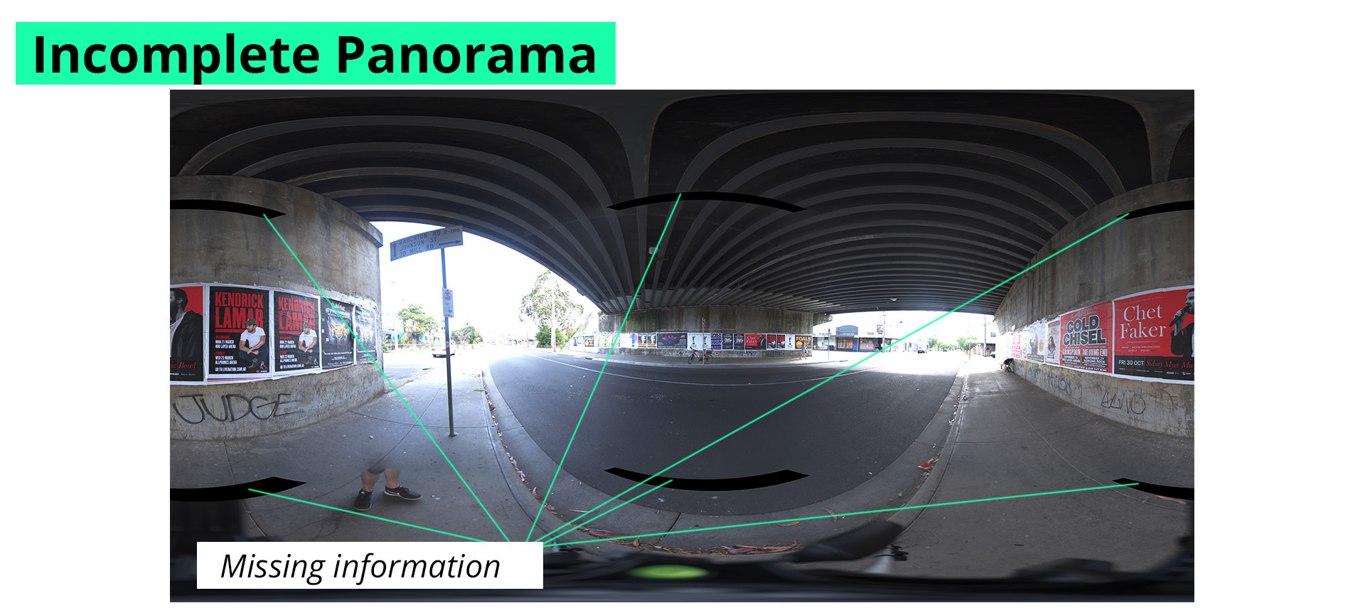
To help illustrate the idea behind a successful rig, let’s break down the problem as a simple visual: The world as a sphere with us in the middle, which at the end of the day is pretty much what we’ll be ending up with, a circular view of the world.
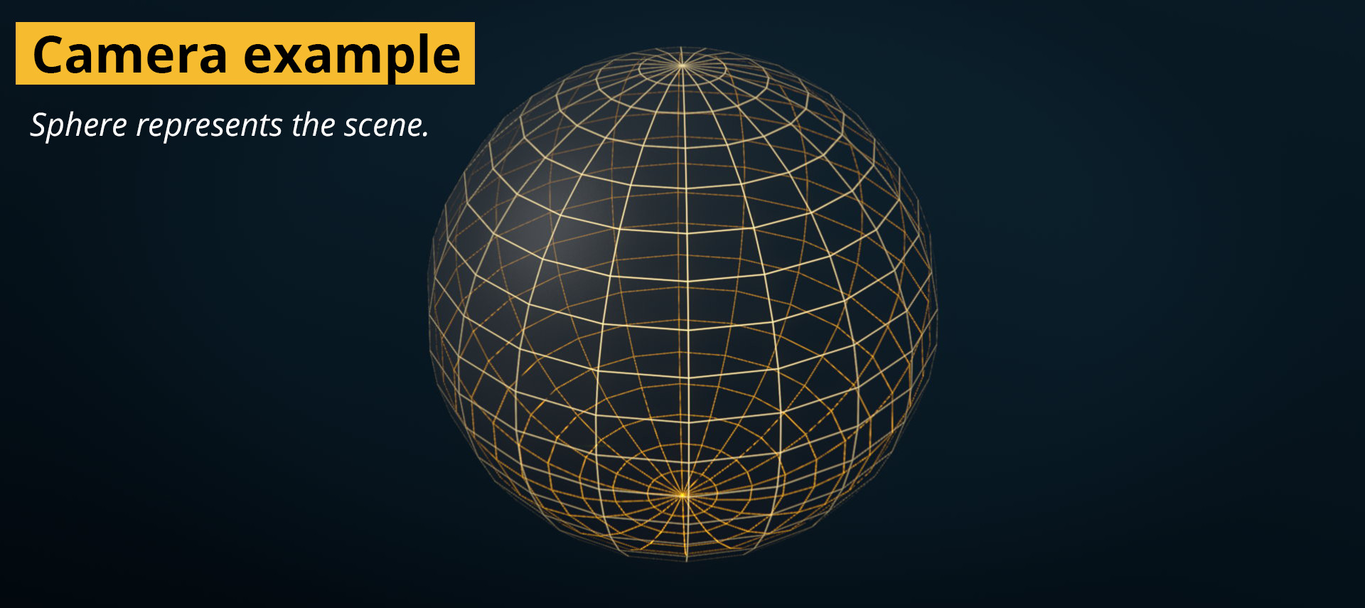
If we imagine the camera as a flashlight in the middle of the sphere, with a beam as wide as the cameras field of view, we can easily see how much we’ll be able to capture and can start to get an idea of how the cameras need to be placed.
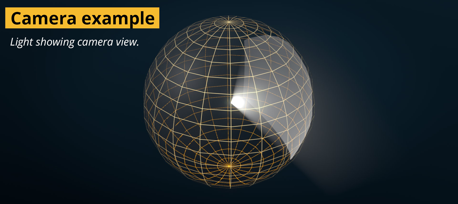
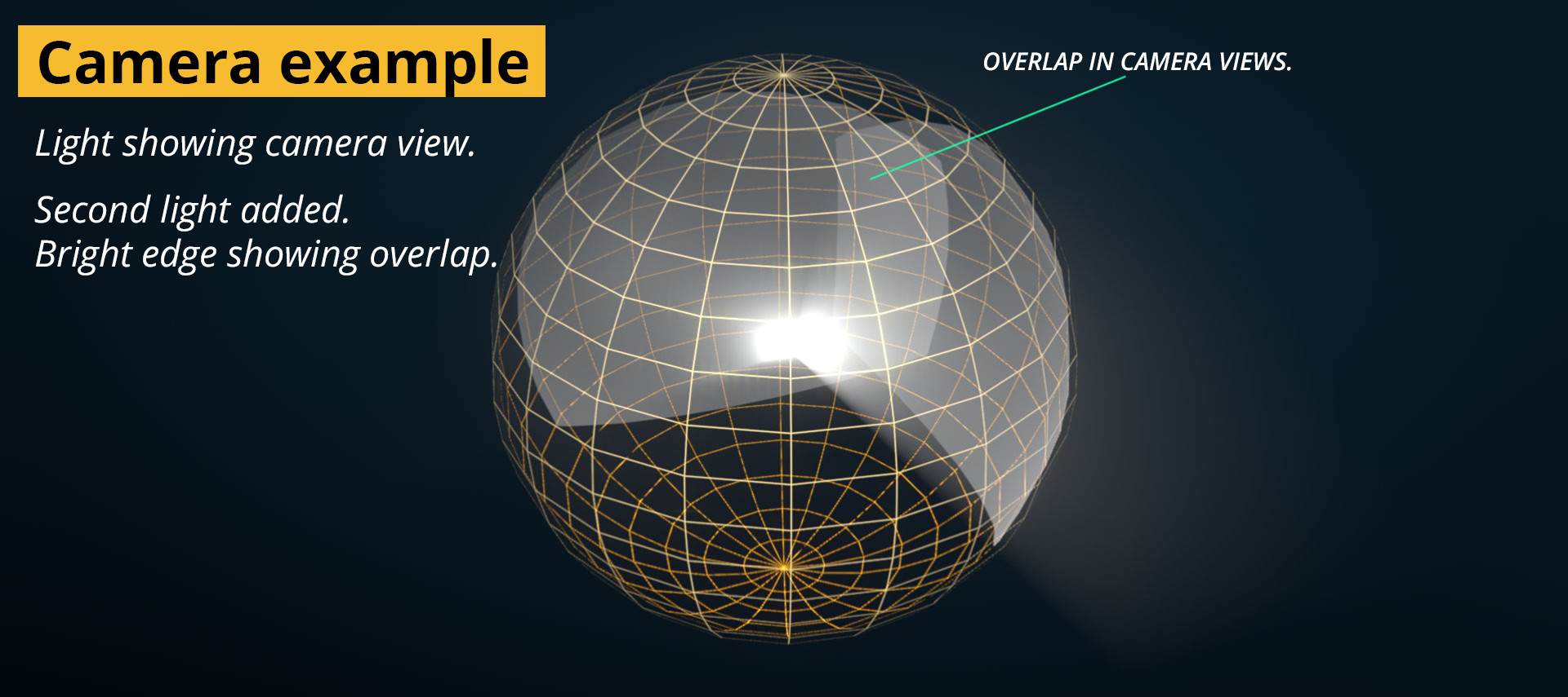
As we add more cameras and rotate them around, we can see how they need to be arranged. As the lights intersect and overlap, the light gets stronger, and we know that every edge should have a brighter edge – because without overlap we wouldn’t be able to stitch them.
Translating it into a real example is most easily done using 3D software. Virtual prototyping is massively helpful for planning and visualising multiple camera arrangements. Free software such as Blender, sketch-up or commercial software such as cinema4D, Houdini, Maya and 3DS Max can all be used to prototype without building anything until all the angles have been taken care of.
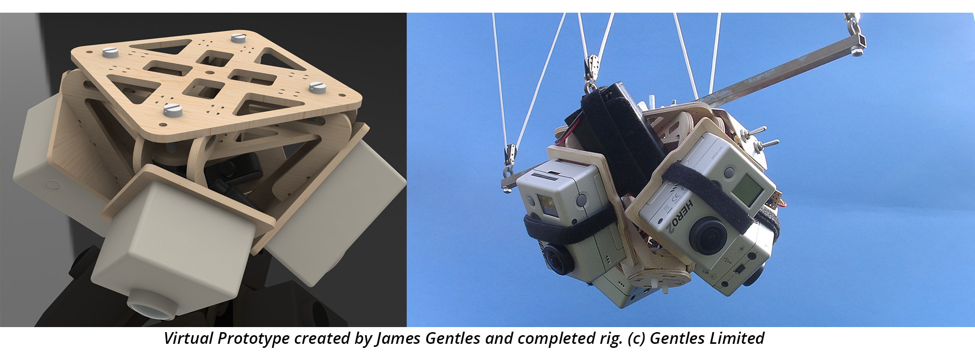
And because the geometry of the cameras are given a physical shape, it becomes far more intuitive to judge whether an arrangement will be able to accomplish the task of shooting 360.
By using an accurate model of the camera, or even just simple shapes that are to scale as stand-ins, it becomes much easier to plan the layout of the cameras. It is possible to test out different camera combinations and lenses without committing any funds. Furthermore, mounting points for tripods and cable management can all be planned here.
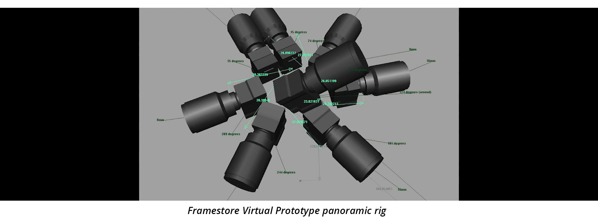
It is even possible to do test renders from the point of view of the camera to know very precisely how much parallax error you will have to deal with and which distances are best for your actors and scenes.
Doing it old School
A step by step for arranging cameras is as follows:
Starting from your lens’ field of view, you can figure out how many cameras you’ll need by dividing 360 by it. For this example I’ll be using a Full frame DSLR set to shoot video, like the canon 6D, with a hypothetical 10mm lens.
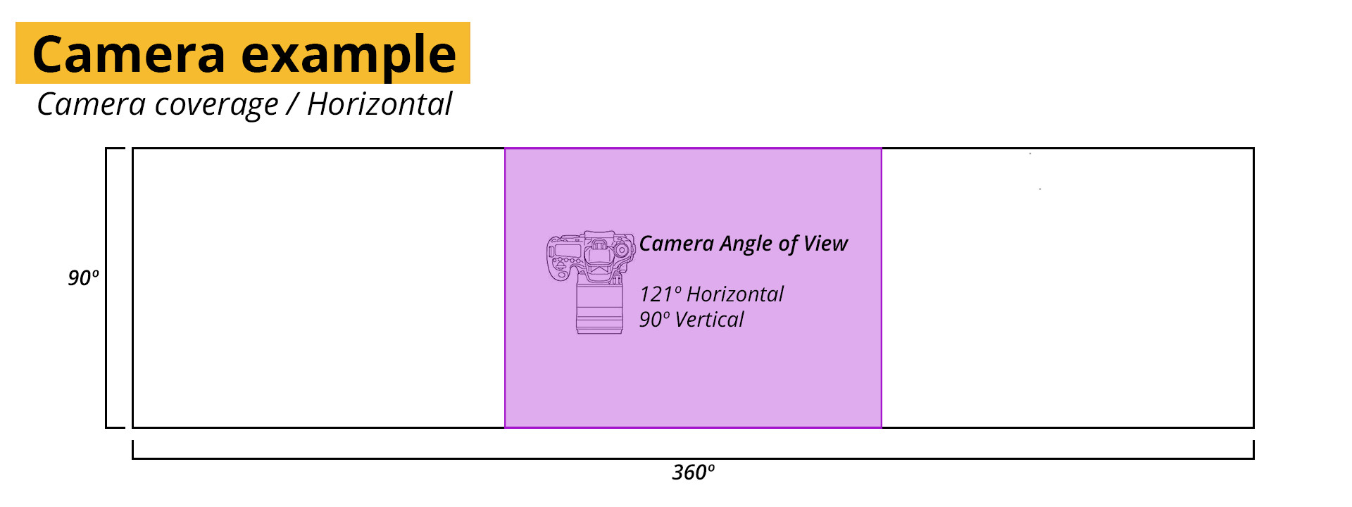
The 6D has a sensor size of 36x24mm, but when shooting video it get’s cropped to 36 x 20.25mm. At 10mm, a rectilinear lens, not a fisheye, would have an angle of view of 121.89º horizontally and 90.71º vertically. Calculated using Frank van der Pol’s online FOV calculator and changing the sensor to a 16×9 ratio.
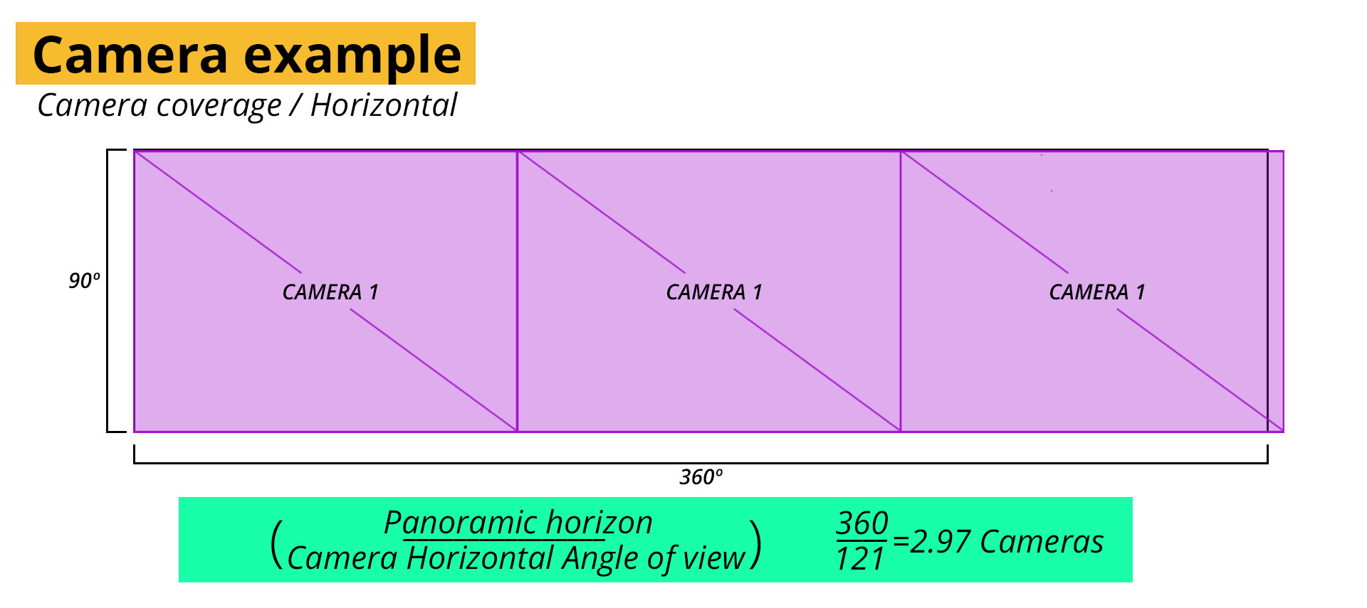
As we can’t use 90% of a camera I’ll round up to 3. The problem is that with three cameras we only have 3 degrees of overlap, or 1º per camera. That would make stitching incredibly hard. So in the interest of better control points, we’ll bump it up to 4 cameras. When using fisheye lenses, 3 cameras often suffice though.
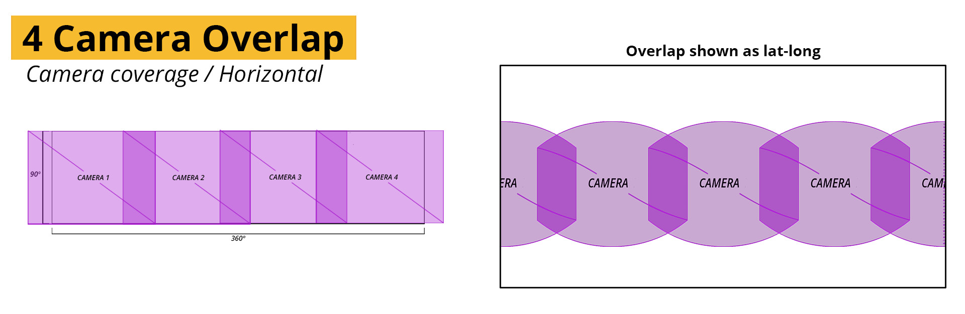
The overlap is much better using 4 cameras, but that only solves the first half and we still need to get the vertical portion of the panorama. Using the same process as before we can calculate the number of images needed knowing that a part of the vertical picture is already being captured by our horizontal row. So we only need to fill in the gap left over.
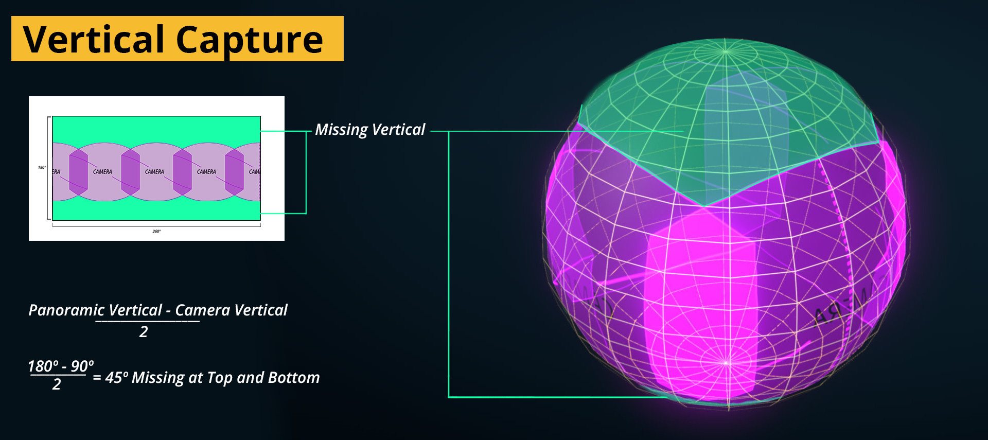
Our camera has a vertical field of view of 90 degrees which means we only need to fill in an extra 90 degrees above and below to capture the the full sphere.
If we add another camera facing up, and one down, the new cameras slot in like puzzle pieces. Again though, we only have a very small area of overlap. Less than 1 º this time.
We could add another set of cameras to increase the overlap, but that would like increase our rig’s size far beyond what is manageable (or affordable). Often, overlap can be maximised by careful rotation of the cameras.
Given that some of our lenses have more than enough overlap, as in the horizontal row. But not enough for the top and bottom, we can split the difference for the overlap by rotating every second camera in the horizontal row onto its side.
Complete coverage, though there are still areas with limited overlap, especially between the corners of all the cameras.
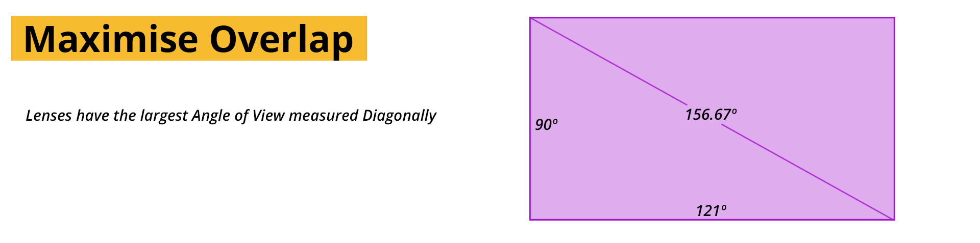
To make the most of each lenses, you can sometimes optimise the layout further by rotating the rig to align the cameras along their diagonal edges. Each lens will have the greatest angle of view between its two opposing corners (top left and bottom right). Doing this will maximise the chances that action will stay localised inside one camera’s field of view, and therefore, away from the seams. The popular GoPro Hero360 rig uses this technique.
All-in-one systems
Cameras capable of capturing panoramic video as a complete package are being developed with some being marketed directly to the public. These are – in effect – nothing more than a neatly designed package containing all the ideas discussed in the chapter thus far. Many are still rumoured, some are being slowly released with many more being developed.
Here is a list of some of the more promising cameras.
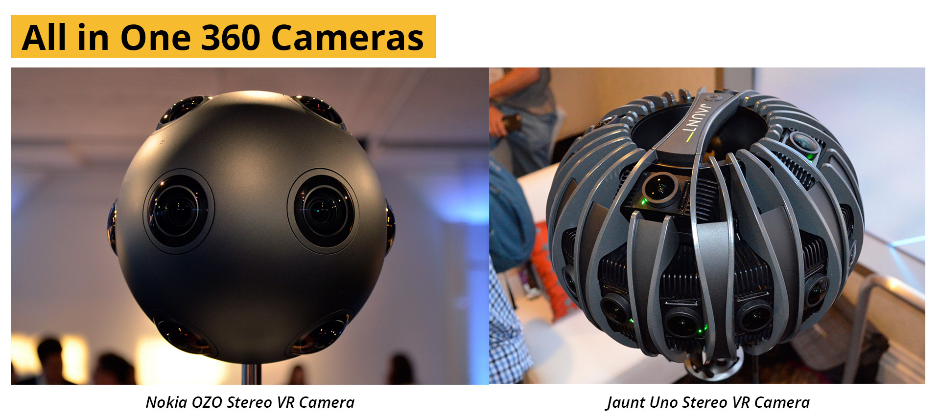
Nokia OZO
A relatively unexpected player in the field of VR, Nokia announced and started manufacture of the OZO. With a partnership with the foundry, a minimalist design and feature packed specifications, it seems like a contender of note. A high dynamic range, hard-wired sync stereo-capable camera. The details of a stereo workflow are handled in the advanced chapter, for now suffice it to say that it is exponentially more complicated than traditional stereo.
Jaunt NEO
Created by the pioneers in the field of Virtual reality films, the Jaunt camera is sure to be a battle hardened camera system. Like the Ozo, the Jaunt aims to be a stereo camera.
Samsung Project Beyond.
Still very much under development, but with a long history of imaging and technology behind them, not to mention their vested interest in VR, the Samsung project beyond is likely to succeed. The camera system has a unique layout for its stereo capture system, but without test footage or released videos it’s impossible to draw conclusions.
Jump True to Google’s size and ability, they have chosen the most complicated format and developed what could be a very exciting and far less parallax prone system. The google Jump rig has a 16-camera gopro array, with a special backpack made specifically to solve the synchronization problems of GoPro. The footage generated by this behemoth would be incredibly large, as due to the sheer size of the frames, almost unusable by most filmmakers. But the true value of the system lies not in the amount or quality of the individual cameras, but more in the workflow google is proposing, an end-to-end computational photography stereo playback solution. It is all very exciting, but too much for one paragraph. The ideas behind it are discussed more fully in the advanced section.
Other Camera Systems
Ricoh Theta
Kodak SP360
Giroptic 360cam
IC Real Tech Allie
Sphericam
Shooting for Synchronisation
Most cameras will capture at a rate between 24 and 60 frames per second, but time extends into infinitely smaller increments. During traditional filming, this is not a problem as there is no reference other than the primary camera for the action. If something occurs really quickly, it generally appears motion blurred, or if fast enough, not at all. With VR it is likely that an action will be visible to more than one camera at the same time, and if the cameras were capturing even slightly offset frames, the action would never match exactly between them. Much in the same way a clapper board is used to synchronise sound to picture in cinema, we can use some cues to synchronise our shots after shooting.
For most consumer cameras there is no way to truly synchronise footage on a small enough scale to be perfect, for large professional cameras a technique known as GENLOCK is used. In a genlocked system, the cameras are all connected with a cable that sends very accurate timing information to each camera and allows them to record their frames at the same time. Synchronisation without genlock is very hard but with some tricks it is possible to get a useable match between all the cameras.
Firstly, ensure that all the cameras start within as small amount of time as is possible. For cameras that allow remote start and stop, like the gopro with the wifi remote, this is generally easier. When remote triggering is not possible, using a few hands and a countdown generally does a pretty good job too. Even with the remote though, a delay is inevitable and some extra steps should be taken to allow for manual or automated synchronization of the footage later.
Using all the “senses” of the camera we can create a number of events that are easy to find afterwards when the footage is being aligned. Specifically, visual, audio, motion and time-code synchronization are all possible. Each is described below.
Visual matching.
Light
Any action that is short lived, and visible to all the cameras at once will be of great use. A bright light, or sudden change in exposure can be used to create a easily recognisable reference point. For example, placing a light-tight bag over the cameras and quickly removing it. Though it would be very hard to do with larger rigs and could easily knock one of the cameras out of alignment. A better approach is to use a remote controlled light, like a camera strobe and create a flash of light. To ensure that the light is seen all the way around, it can be reflected onto a card or umbrella on the other side. More complicated solutions such as an LED light strip arranged in a circle (think hula hoop) can be used, easily being held in front of all the cameras at once, switch on and off and removed. As a side benefit, this will also serve as a benchmark for the quality of the alignment between the cameras.
Movement / Motion
Movement can be used to align footage too, using optical flow and motion tracking algorithms like those used to create motion blur or slow down footage. To create an event that such systems can track, the rig needs to be rapidly moved, usually rotated. This creates a sudden flurry of movement that will be similar in intensity for all the cameras.
In the end, any uniquely identifiable, short lived but pronounced visual cue will be useful – provided it is visible to all the cameras at once.
Sound.
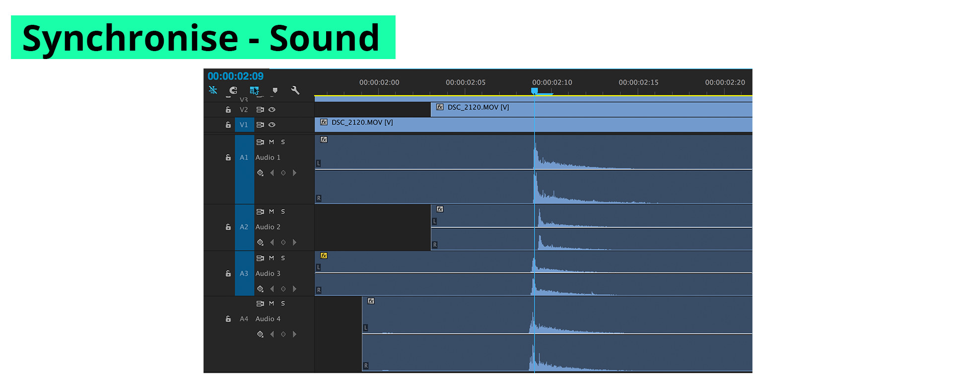
Sound as synchronization is widely used today for multi-camera productions such as studio and reality television and documentary films. For sound to be an effective means of aligning footage its best to use a short, loud and uniquely identifiable source. A clicker, clapper-board or even a whistle can all generate enough of a difference to the ambient sound to be easily found afterwards. When the scene has a lot of distracting noise, like a concert, ocean or even strong winds, it may prove impossible to create enough of a differentiation sound for synch. It is therefore good practice to use more than one method for synch.
There are a number of sound synching plugins available, including the wildly popular pluraleyes by Red Giant. Sound can be synchronized manually as well without much experience. As waveforms will appear visually similar between all the different cameras, the footage can be slid around until the waveforms are aligned. This can be done using any video application.
Single Camera Workflow
Special projects that don’t need same time capture of the scene can be captured using a wide-angle lens on a panoramic head tripod. Some projects have done so quite effectively.
The workflow can be described as a series of discrete setups, one at each rotation of the camera. By marking off the angles that the camera will see, and keeping important action clear of these areas – a concept can be broken down into far more manageable “chunks” for filming. It also allows the director to be present on set during filming, a rare luxury in VR.
Furthermore, the action can be done as traditional takes – meaning all the action doesn’t need to happen perfectly all the way around. You can cherry pick the takes from each of the angles that best match your intentions. For stories with more complex storylines or difficult to repeat actions, this may very well prove the way to go.
Special purpose projects or concepts that don’t have any need for temporal consistency can be created using this same logic. Very interesting results can be created using only one camera and a little planning.
You don’t always need video!
In some situations it might not even be necessary to shoot video at all, areas that are unchanging and without action like the sky or the floor, or even parts of the set can often simply be photographed and included in the panorama – alleviating some of the data strain of video. This idea is discussed more fully in the next chapter.
Further Reading
Jim Walters: Camera setup for shooting VR or Immersive Video
Bit Depth and Image Formats
Resolution and Virtual Reality, it’s all relative
Why 8K isn’t enough for perfect VR
HDR Video Compression Using High Efficiency Video Coding
HIGH DYNAMIC RANGE IMAGE AND VIDEO COMPRESSION
Technical notes on Fisheye Lenses
Calculating Parallax
Field of View Calculator
Entrance Pupil Database for Various Lenses
HDR encoding, Colourspace and Gamma
SITE LINKS
INTRODUCTION CHAPTER 2 / THE BASICS CHAPTER 2 / CAPTURECHAPTER 3 / THE STITCHCHAPTER 4 / POST-PRODUCTIONCHAPTER 5 / DISTRIBUTIONADDENDUM / ADVANCED