
Stitching in VR quite literally refers to taking all the footage from all the cameras in the rig, and arranging them into a single image. Although this might seem like a daunting task there are a number of tools already available, with more advanced and free versions becoming available every few months.
Before stitching begins though, it is important to synchronise your footage, using any of the methods in the previous chapter. Most of the software packages will allow you to do the synchronization as part of the stitch, but if this is not the case it might be better to use a more sophisticated editing program like After Effects to align and export a new sequence beforehand. If the cameras started more than a few seconds apart, it might be advantageous to create a trimmed take as well, as large gaps can lead to false positive synchronisation.
Quick Navigation
Deal Breakers for Stitching
Step 1. Image Distortion
Step 2. Feature Matching
Step 3. Straighten the Horizon
Step 4. Colour Correct and stabilise
Step 5. Export
Manual Stitching
Manual Stitch: PtGui and After Effects
Manual Stitch: The Foundry Nuke
Downloads / Assets
Further Reading
Once synchronized, it’s time to start stitching. Stitching is a three part process that involves the removal of any distortion on the images introduced by the lens, matching common features in the footage between the cameras, and aligning the frames into a lat-long.
All three of these steps can be automated to a large extent with varying levels of success using special software like PtGui, AutoPanoVideo and Hugin. PtGui and Hugin were not created for video, but both can be set to run as a batch process on a number of frames. Many more software packages exist and a list is included at the end of the chapter.
Automated stitching
Automated stitching is a massive timesaver, not to mention simplifying the process considerably. At present, most stitching software works by analyzing a specific frame, creating a template and combining all the frames of the shot using that template. This unfortunately means that they do not take into account the fact that the scene might change as actors or the camera-rig moves around. As the features are matched based on their distance to the camera (the parallax problem again) if the template was created from an inaccurate set of features, the resulting seam lines may be less than perfect. The workflows shown below try to leave some flexibility in the workflow by using the templates as a base while still allowing intervention down the track.
Many of the applications are however intended to be one-stop-shops, meaning that they take footage in and deliver a final, distribution ready video at the other end. Distribution ready here meaning web-compressed, with very few offering a way of working with higher bit-depth or dynamic range source material. But if your needs are met, it may very well be worth the loss of fine-grained control.
For times when the loss of control and colour information is unacceptable, some may want or need the flexibility to control the merging of footage. The methods for creating a stitch by hand can vary immensely though, depending on software, artist skill and the cameras used. A few possible approaches will be discussed more broadly at the end of this chapter, using the Foundry’s Nuke as well as Adobe’s After Effects as an example. Though once the steps are understood, they should be adaptable to whatever tools you might have at your disposal.
Deal Breakers for Stitching
There are a number of problems that may pop-up in the course of filming, some are a nuisance, like exposure changes, and other can render a shot completely unusable and should be avoided at all costs. Some have been mentioned in the capture chapter, but they bare repeating.
Everything the same
Cameras that capture at different frame-rates can not be stitched automatically by some software packages, like Autopano Video.
All for one and one for all
If one camera’s battery dies, the whole shot will usually have to be scrapped. Sometimes it is possible to salvage such a situation if the camera isn’t pointing at the action – in which case a still frame can be used to fill the hole if there is no camera move.
**Corrupt footage. **
Less of a concern with professional cameras, but a piece of footage that becomes corrupt during saving, copying or processing will have the same effect as a dead camera. For this reason it is best to keep takes short if possible and keep a backup of the footage.
Missing shots and mismanaged footage.
Stitching is as much an exercise in project management as it is a technical adventure. Camera footage should be labeled and organized correctly and fastidiously- if a piece of footage gets lost or misplaced it can be virtually impossible to guess where it is supposed to fit in. Mismanaged takes and camera numbers will also render any template useless.
Step 1. Image Distortion
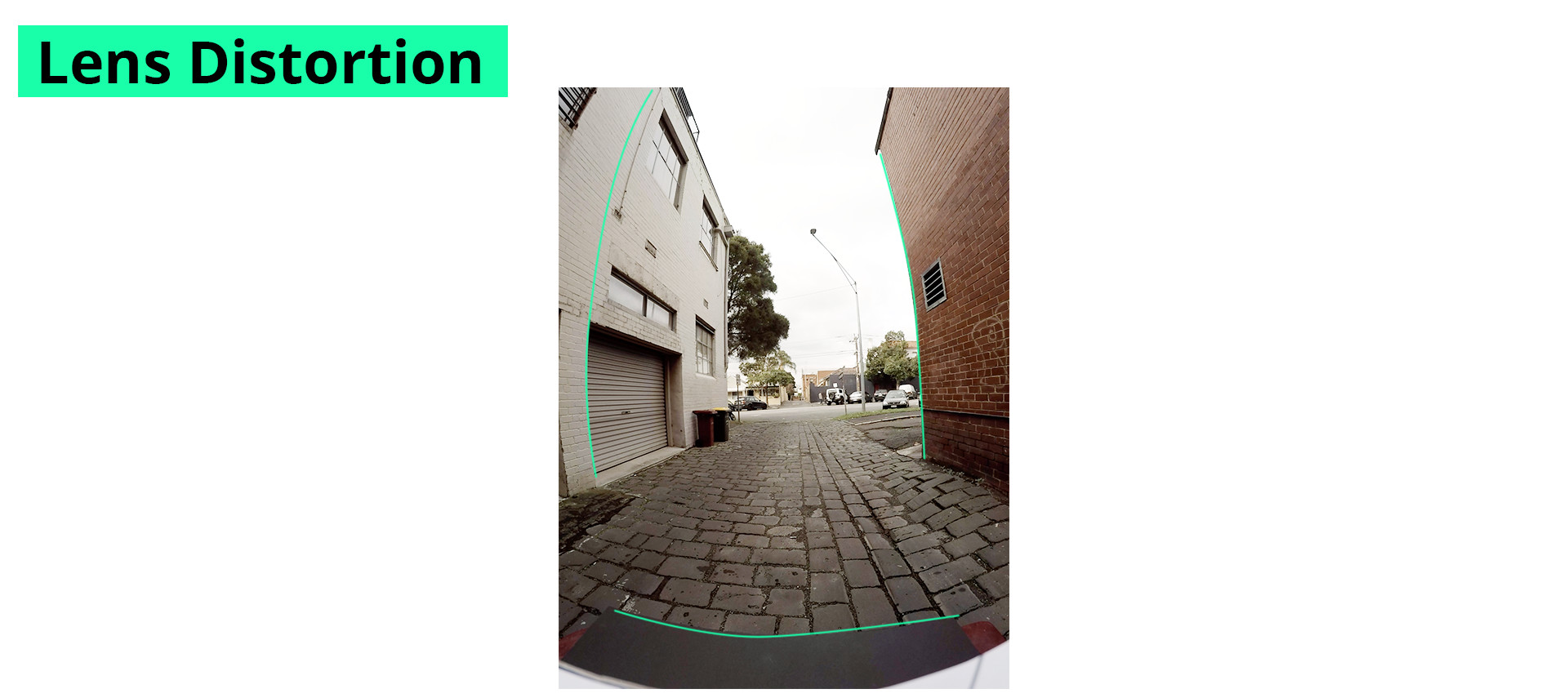
Distortion is an inescapable but generally manageable problem present in photography. Every lens ever made has some degree of distortion present, and it is usually more pronounced with wide angle lenses and at it’s most obvious with fisheye lenses. It is easily spotted as a curving of straight vertical or horizontal lines in the picture. As the distance from the center of the picture increases, so does the level of curvature.
Although this distortion can sometimes add to the aesthetic of a shot and may under regular circumstances even be wanted – for VR it needs to be removed.
Because we will be combining several shots together, we need to be sure that the proportions and relationships between things in the frame can be trusted and are reliable and that means them not skewed, literally, by the lens.
Removing distortion is most often an automatic process. If the lens is popular and being used by the community often, as with the gopro, the way the lens distorts the image may be well known and can be removed using preset values.
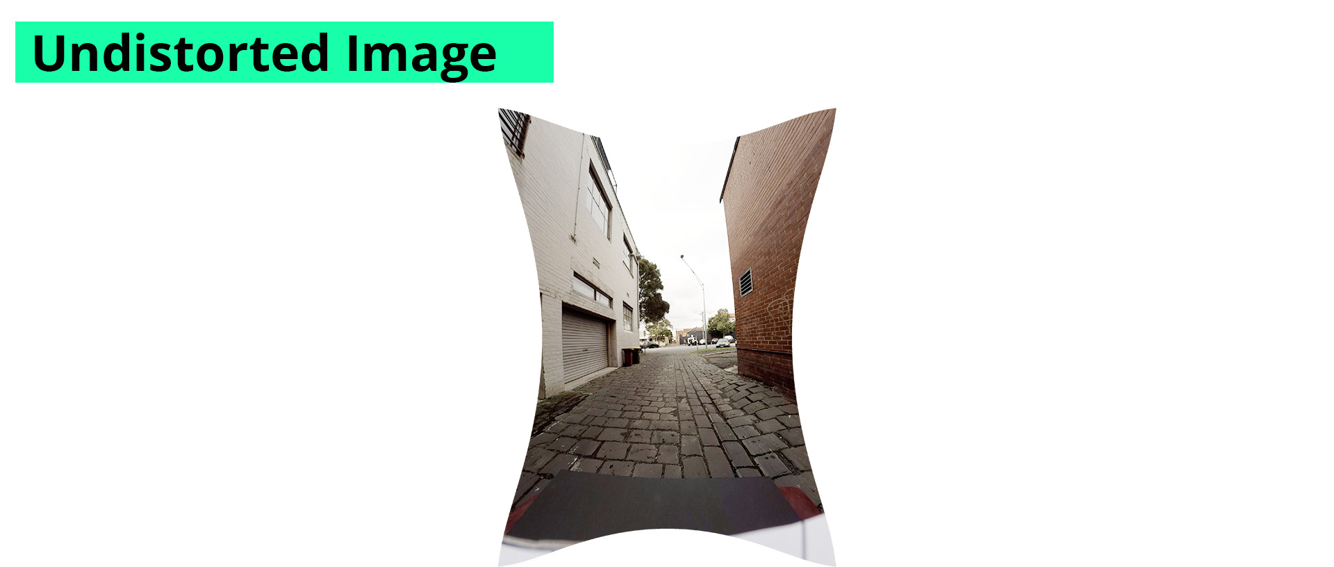
Removing the distortion leads to a strange looking pictures though, because the image is in fact stretched out as though pulled from the corners to straighten out the image. Most lens distortion tools assume that we would have no use for those edges and simply crops them out. For stitching VR those corners could still provide lots of useful information so it’s best to keep them.
All stitching software will account for the image distortion in one way or another, with varying levels of accuracy, but rarely with bad results. Unless you’re planning to stitch the footage completely by hand, it isn’t necessary to worry about the distortion, provided your software package of choice is capable of removing it.
Step 2. Feature Matching
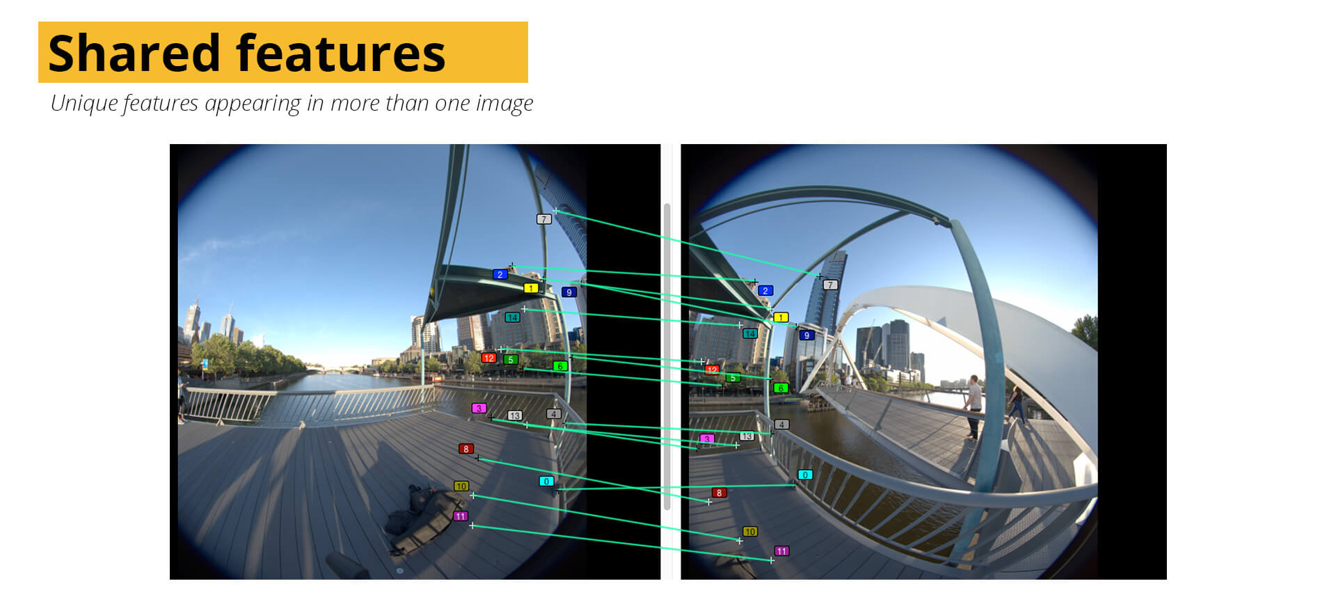
Automated stitching needs some way to understand how all the jugsaw pieces of footage are supposed to be arranged. Without understanding what the scene is about a series of control points need to be defined. Control points are features in the scene that are seen from more than one camera. Generally the software will be able to find features automatically, though this relies on the scene. A good feature will stand out from it’s surroundings and be unique enough not be to confused for similar points. There also needs to be quite a few between each pair of cameras to ensure enough information to combine them. If there aren’t enough details, it might very well be your job to instruct the software over shared features.
Certain subjects are hard for automatic feature matching, specifically any repeating patterns or high frequency details, like sand or small tiles can lead to false matches. Also, features that may appear in different places depending on where they are viewed from, like reflections on water or highlights on cars are another source of false matching. Before committing to an automated stitch it is best to give the found features a visual inspection for any bad matches.
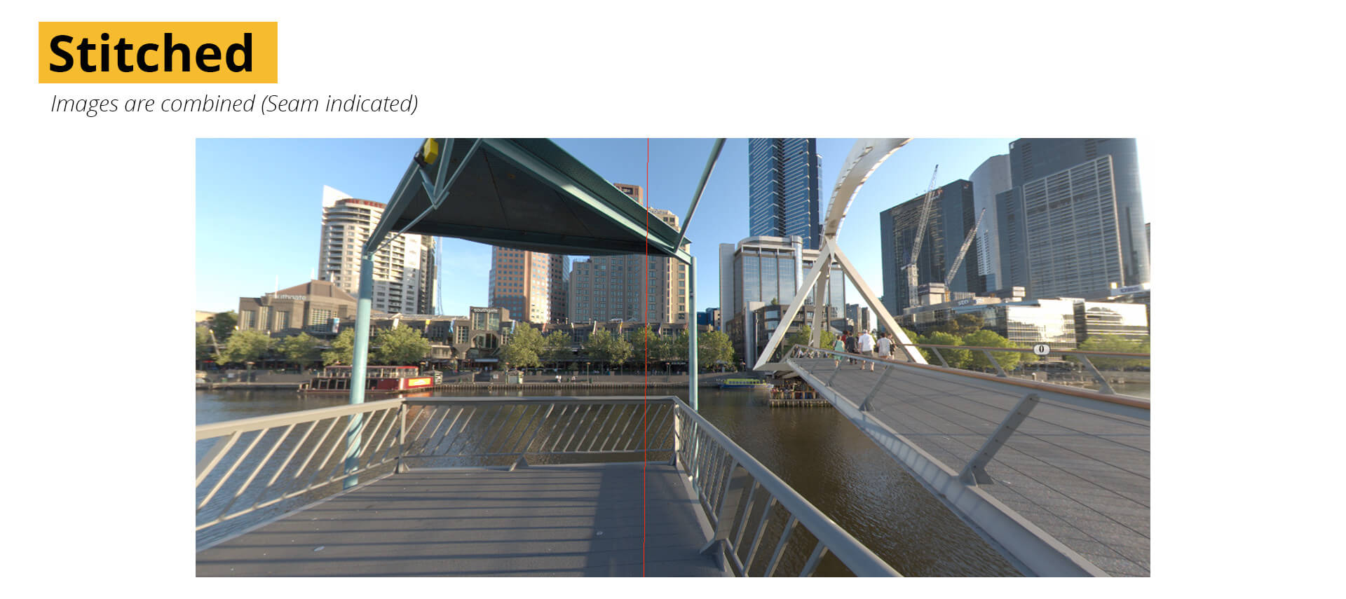
The features will guide the stitching, and the software will align them – warping the images so that the features are placed one over the other. The different images will then be gradually faded from one to the other, usually with some degree of user control though always in a straight line. This area where the panorama fades from one image to the next is often called the “seam”.
It is important to note that although the instinct might be to use the first frame of a sequence to create a feature-matched template, there will be times when the first section may not have sufficient shared features. A good rig that doesn’t allow for any unwanted movement of the cameras will have a characteristic that we can exploit to solve this problem – consistency.
To use the consistent arrangement of cameras to our advantage, a stitch “template” can be created beforehand by shooting a short piece of footage using the rig in a space with a lot of static detail. The template simply remembers where each camera was pointed, and how the images blended together. When using a template, there is no need for feature matching.
As long as the same cameras are used in exactly the same spots on the rig, the template can easily be used over and over with reliable results. There is a catch however, as they are unfortunately not perfect. Because they match features, and those features are at a specific distance from the camera, if the distance changes – whether between setups or during the course of filming- the template will start to “drift”. Edges and details that might have lined up would no longer do so.
With that said, templates are still invaluable as they offer a solid and knowable starting point for a manual stitch. In fact, when shooting in difficult areas that won’t have enough detail for an automatic stitch, it may be the only way to get a stitch at all.
The Gopro Hero360 series of rigs are supplied with a number of templates, that match certain gopro aspect ratios and resolutions.
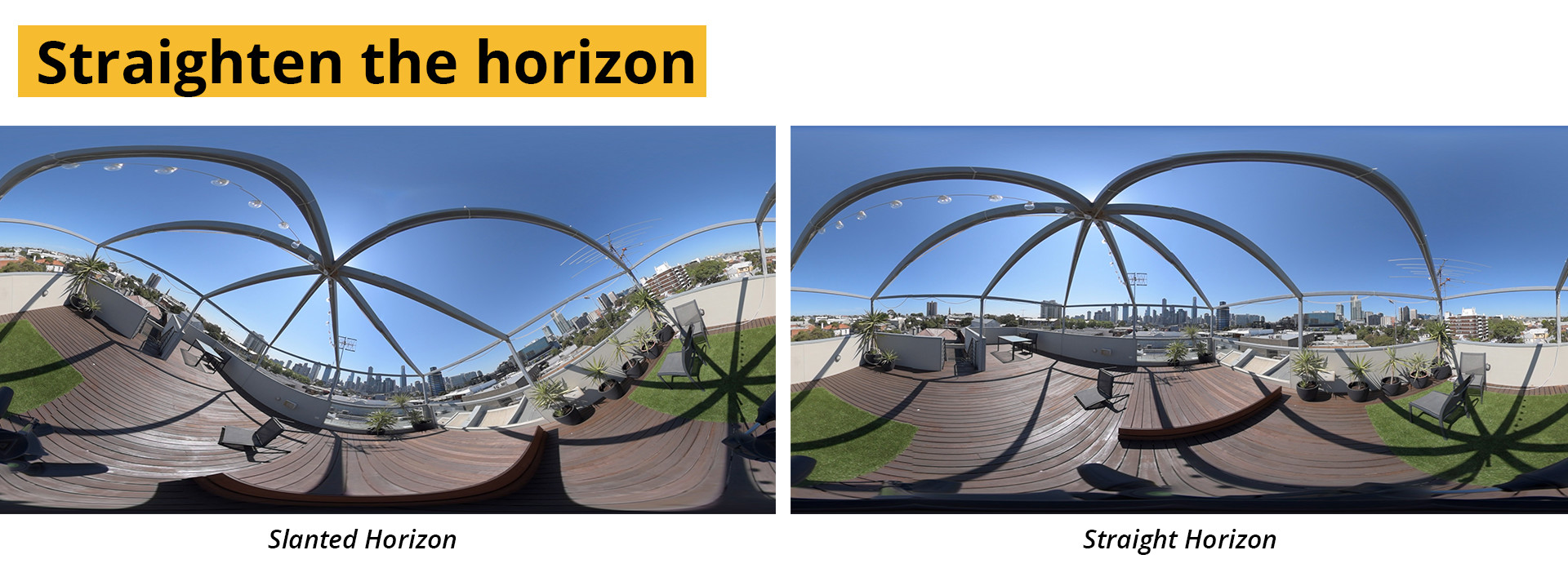
Step 3. Straighten the horizon
Once the panorama has been stitched, the horizon line is usually at an awkward angle. This should be corrected before the scene is exported. A skewed horizon line is an almost guaranteed source of motion sickness for your audience.
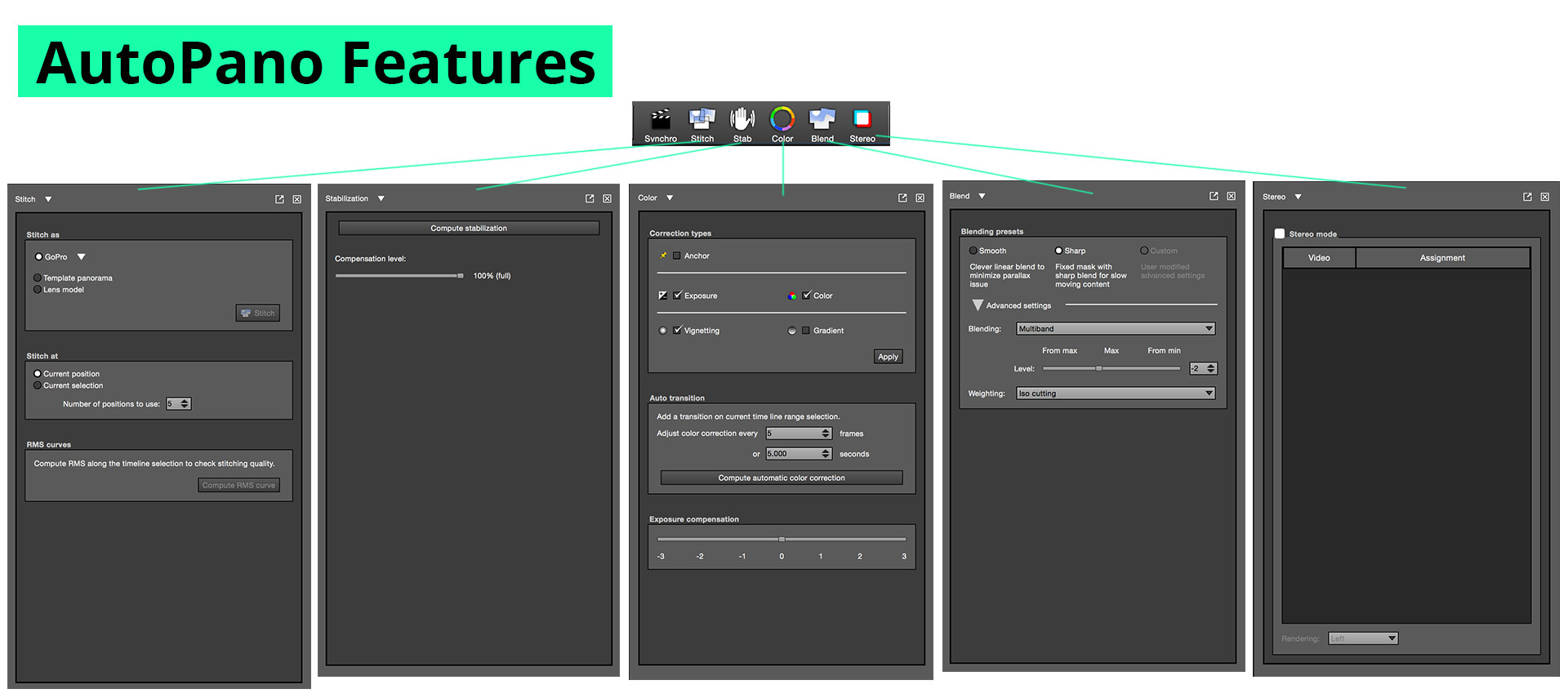
Step 4. Colour correction and stabilising camera moves
Although discussed in the next chapter on post-production, some stitching applications allow for some of the steps to be incorporated during the stitching phase. To correct for exposure differences between the cameras some offer exposure compensation and white balance adjustments. Some packages, notably AutoPanoVideo even offer the opportunity to stabilize the panorama if the camera was moving – removing any rotation. These are generally automated processes which means that when they work, they’ll make your life easier, but with a lack of artist intervention – if the results are less than optimal there isn’t a lot you can do.
Step 5. Export
From here-on the process is straightforward. Choose the size of the final panorama, choose the export format and wait for the process to complete.
The panoramic footage can now be freely edited using any editing program, as long as the actual scale, position or rotation of the panorama isn’t changed in any way. It may be hard to see how scene will look to the final audience, but with some practice it becomes easy to read a lat-long with the same efficiency as any other piece of footage. If no further post-production is needed, the file can be prepared for delivery.
Manual Stitching
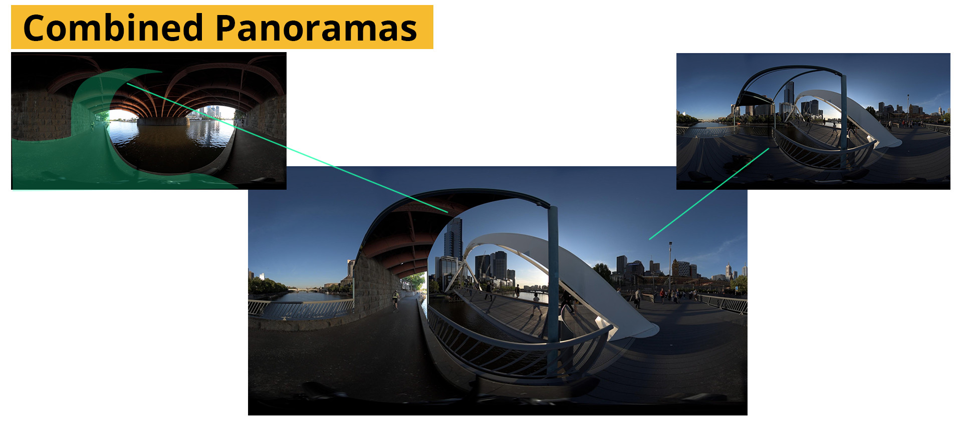
Given how complex it is to synchronise, match, align, correct, stabilize and stitch footage you might be tempted to ask why go manual at all? The answer is quite simply control. Control to make decisions about where seams are located, their shape and width. Choosing to favour one image over another as an actor nears the edge of frame for example. Furthermore it allows for additional warping to counteract the effects of parallax, and the ability to control exposure, colour and stabilization in a more direct way. Shots that may be impossible to stitch using automatic solutions will need to be done by hand, for example when combining to scenes that were not shot at the same time or even different locations.
Samples of the footage used and all the final project files are available for download at the bottom of the page. In the interest of smaller file sizes (and hosting) The clips have been trimmed.
Manual stitching is not for the faint of heart, but neither is it insurmountable. All of the steps done by automated solutions exist to some degree in any modern compositing package, and some of the steps (like feature matching) can be used as a starting point for a manual stitch.
By focusing on the three steps of stitching (distortion, matching, and merging) two possible solutions will be presented. Starting with a simpler method, relying heavily on PtGui for template creation and using After Effects, as well as a more advanced workflow, using Nuke to stitch a scene by recreating the cameras that captured it.
Manual Stitching: PtGui and After Effects
After Effects is a 2.5D compositing and animation package from Adobe. Although there is an extensive toolset that covers a lot of the needs for compositing and motion graphics, the lack of a true 3D workspace makes is hard to stitch footage completely within After Effects. But through using a technique usually reserved for visual effects work, it is possible to translate templates created in PtGui to After Effects using UV-mapping.
This workflow is based on the established workflows for mapping textures onto 3D geometry after they have been rendered. To explain it briefly, the process needed to assign a flat texture to a 3D object requires that the texture be “wrapped” onto the model. The co-ordinates of the wrapping is stored as a UV map. Each part of a UV map refers to a location on the 3D model and is stored as a flat image. We’ll just be using it to move a flat image around – no 3D required, but it’s helpful to know how it works.
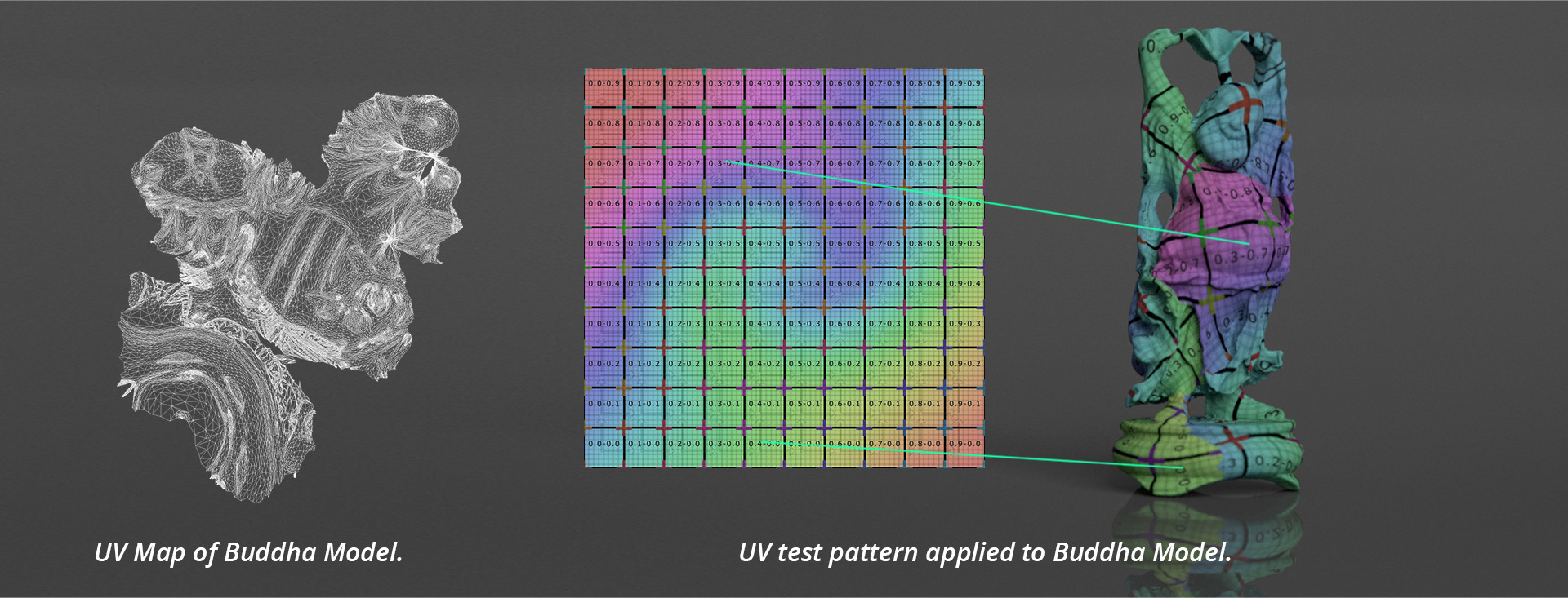
By drawing on this idea we can use a texture with a unique colour at each pixel as a guide for transferring the coordinates between PtGui and After Effects. To handle the vast number of pixels present in a video frame we’ll be using a 32-bit image.
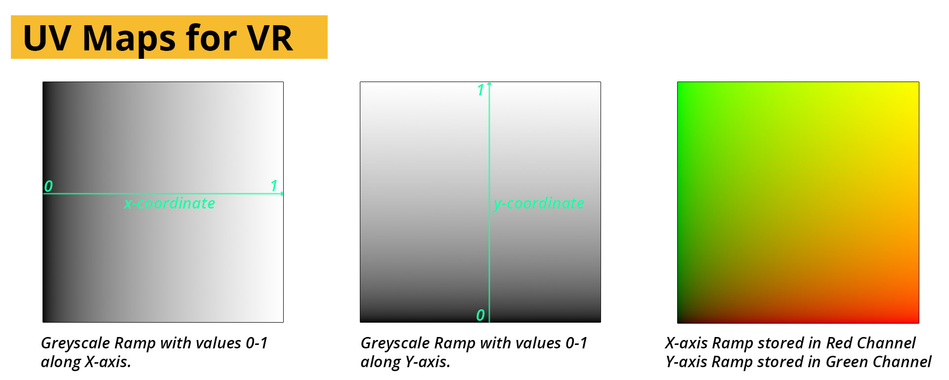
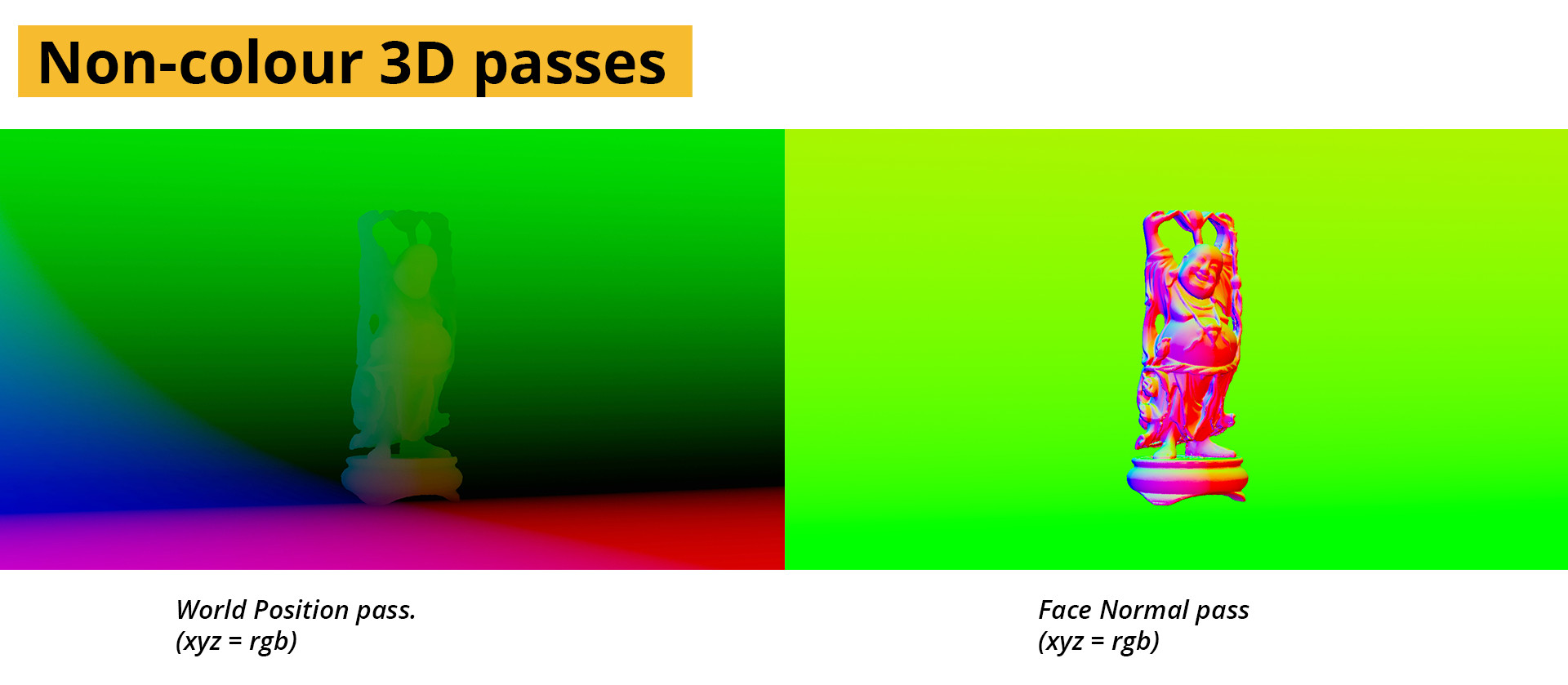
A linear gradient running along the x-axis of the image will become our reference for the horizontal position of the pixels in the footage. For the vertical axis a gradient along the y-axis will be used. To store both independently in the same file, we’ll use the red and green channels of an OpenEXR file, with the other channels empty. This arrangement is the industry standard for presenting UV-maps. Interestingly, the same logic of encoding is used for Normal and vector maps creating by 3D software, though both of these include a z-axis usually mapped to the blue channel as well.
By using this arrangement, the software can reference a texture’s displacement in 3D space even after the render and can be used to transfer additional texture details onto pre-rendered footage.
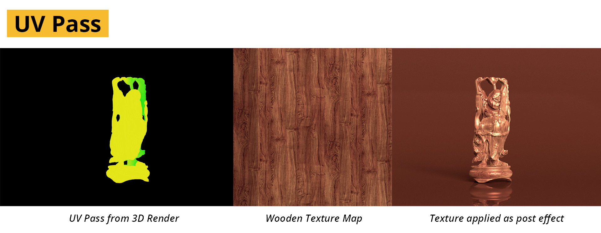
We’ll use this to store the position distortions done by PtGui on each of our footage items and in so doing – be able to track where each pixel ends up in the final panorama. By exporting this map back to after Effects and using RE:Map by Re:vision software(the makers of the ever popular Reel smart Motion Blur) we’ll be able to very accurately warp our videos to the correct locations.
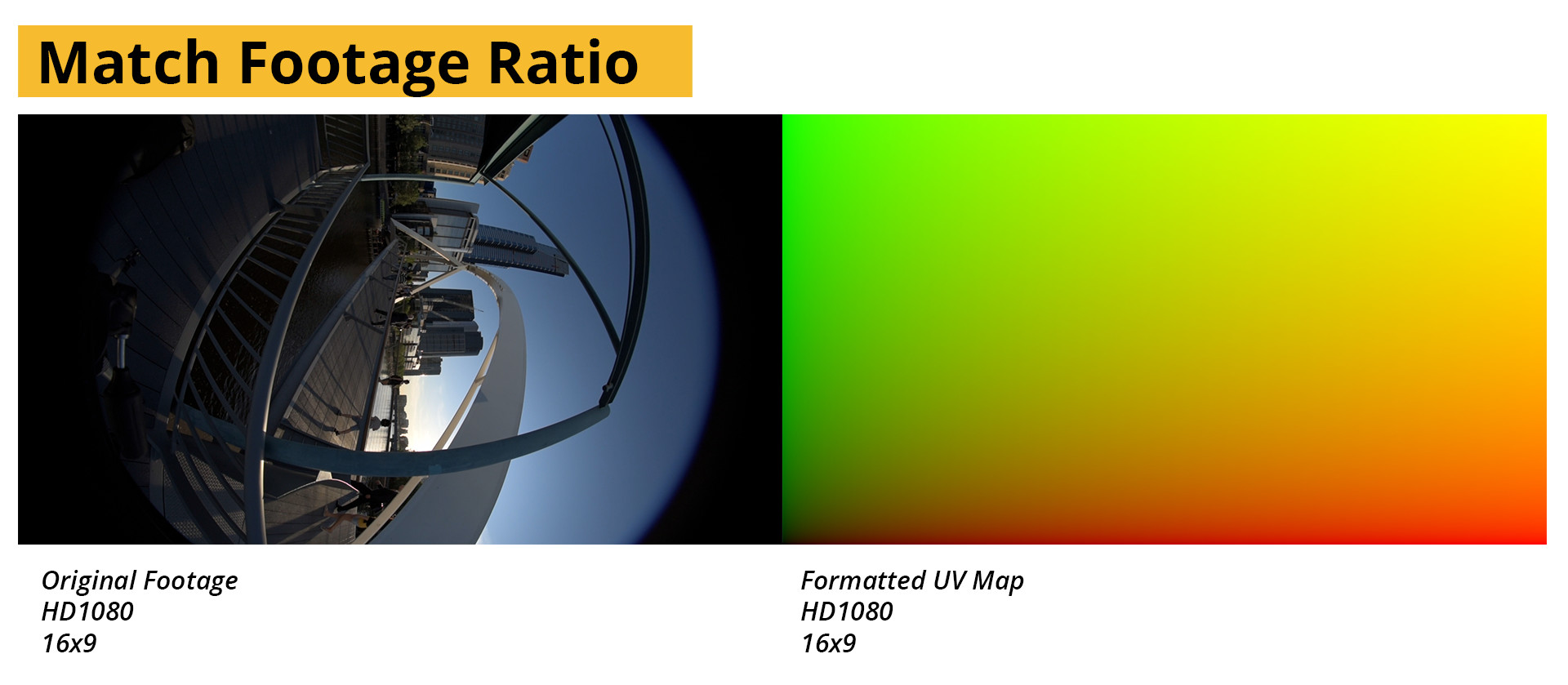
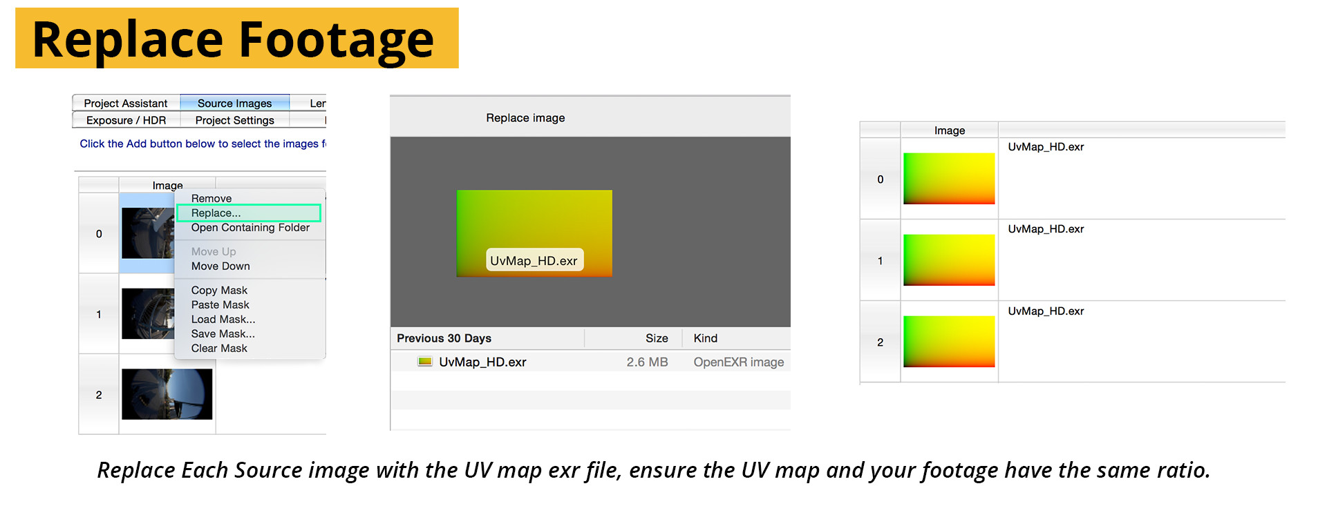
The two important factors for the UV-map are that it is in the same ratio as the footage, and 32-bit. I’ve included a number of pre-prepared UV-layouts in some of the popular shooting formats in the download section at the end of the chapter. They are named as: Specification_ratio_resolution.exr e.g. HD_16x9_1080.exr
To allow us to export the template to after effects for further processing, create a stitch as normal using PtGui. A guide can be found here. Do not optimize the exposure, or change the colour in the picture at all. That part of the process will be handled in After Effects.
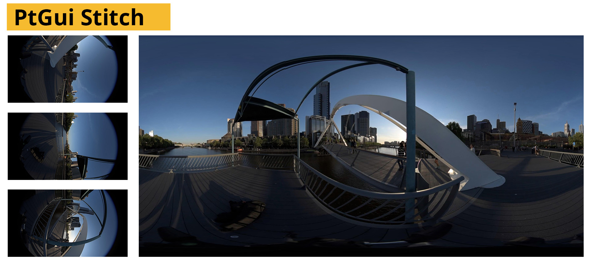
Once the stitch has been made, but before exporting, swop to the images tab and replace all the footage files with a UV-map with the same aspect ratio. Ignore the warnings and do not align the images again.
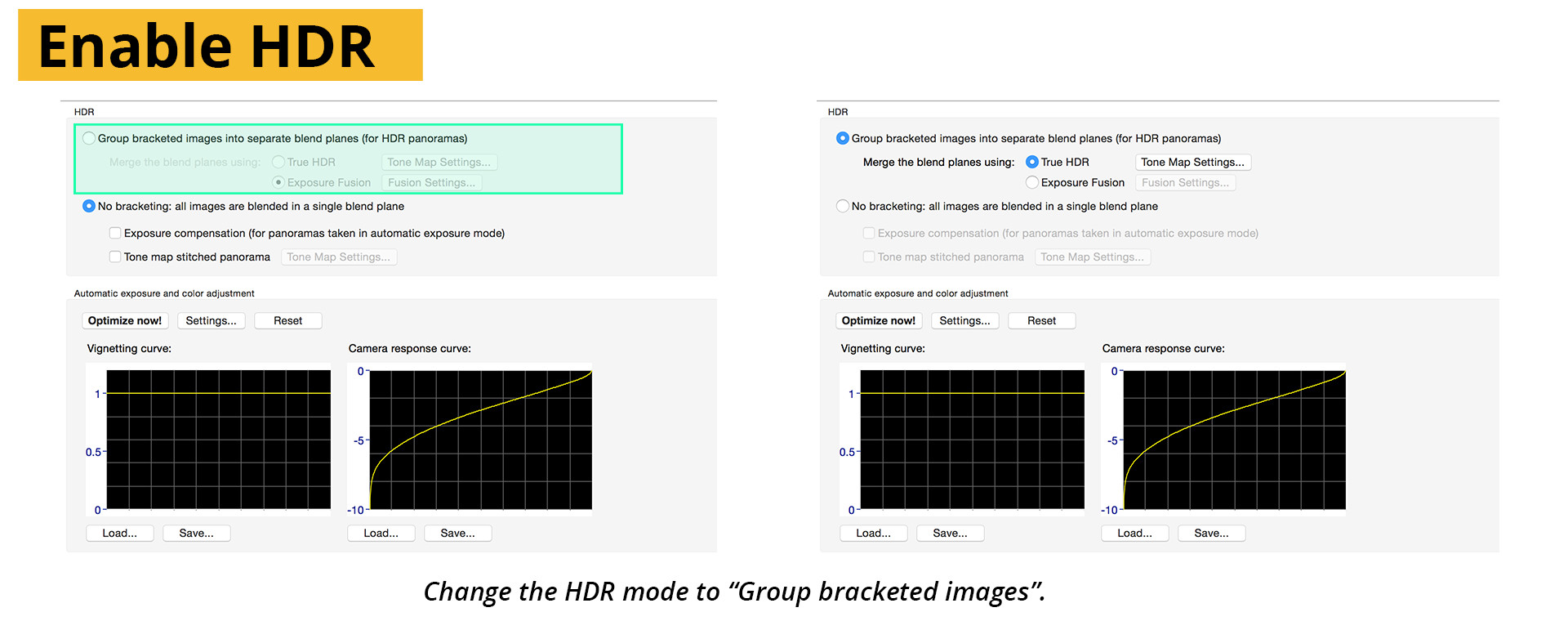
Change to the Exposure/HDR tab and make sure to tick the HDR box as below. The footage used in this example was shot with a Nikon camera and is low-dynamic range, but the UV-map is in fact very high Dynamic range and to preserve all the information we’ll need to go out in the same format we came in.
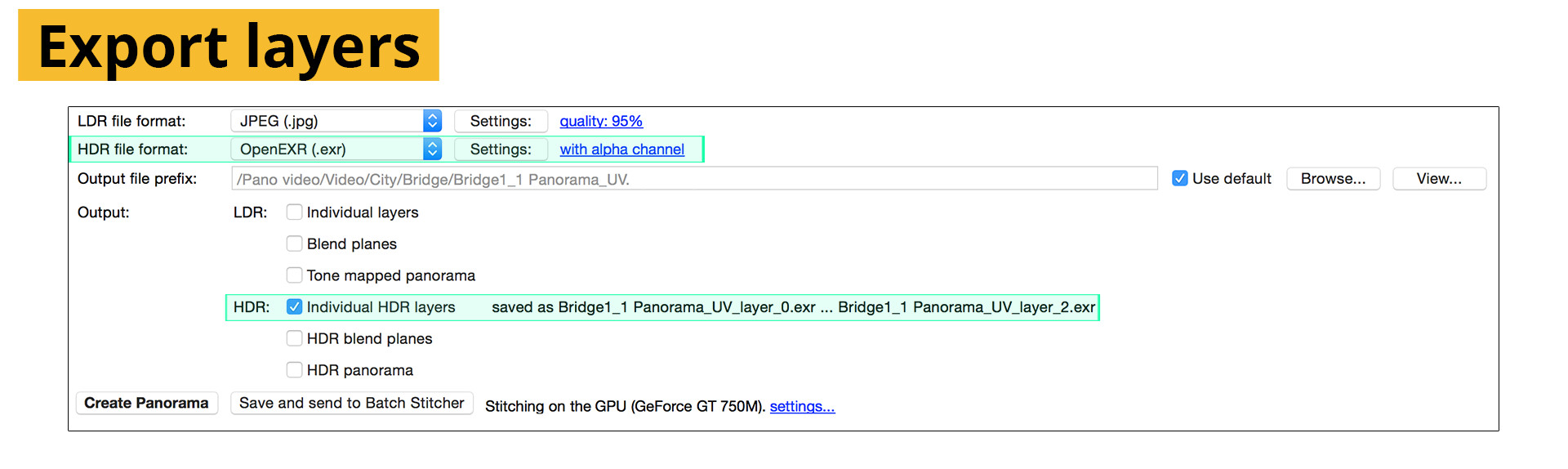
Swop to the export tab, you should have an LDR (low dynamic range) and HDR (High Dynamic Range) option visible for the export. Select Individual layers as your export type. We’ll be using each image separately, allowing us to control the blending ourselves. Make sure “with transparency” is enabled in the export!
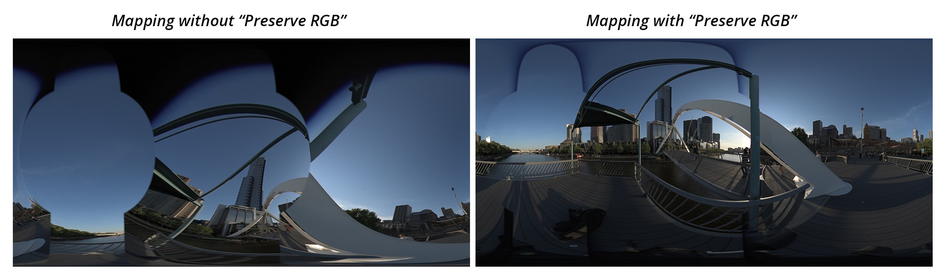
In After Effects, open a new project and change the project settings to use 32-bit. This will ensure our EXR files can be used without artifacts, and increases the quality output overall. Import the layer exports from PtGui, and under the color management tab of Interpret footage tick the “Preserve RGB” option. After Effects automatically applies a gamma correction to footage on import, especially for linear, high dynamic range images. Although useful at times, it changes the values of the pixel colours and since our pixel colours are actually referring to a position in 2D space, it changes the position of our footage files.
To Map our footage to their correct spots in the panorama we’ll need a plugin that can read the UV data. Some plugins that can do this are: Re:Map, Youveelizer and ft-UV
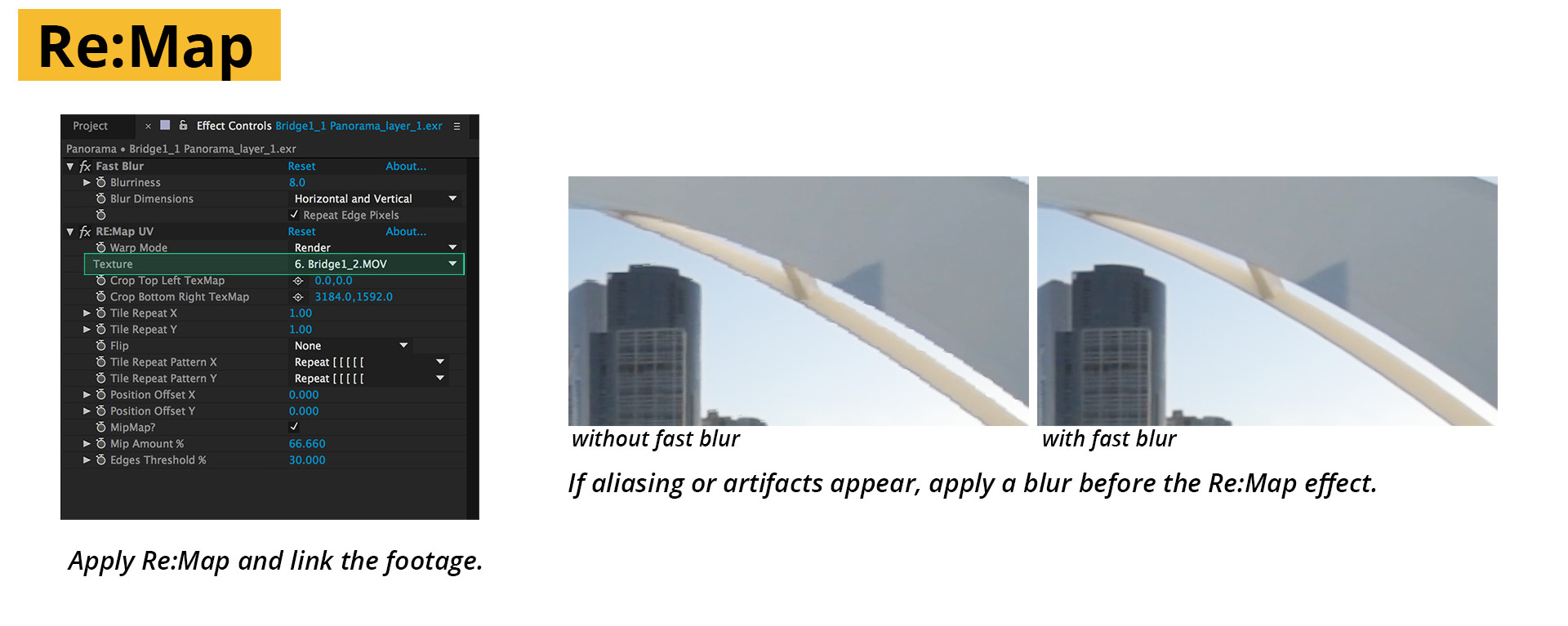
Add all the UV layers to a new comp with the same dimensions as the final panorama and apply Re:Map to each one.
Add all the video files to the comp and turn off their visibility. We won’t be using them directly.
Match up the footage to the UV maps under the “layer source” of each UV layer’s Re:Map plugin. The footage will appear instead of the red and green in the viewport. If the panorama looks wrong, make sure that the right layers have been chosen.
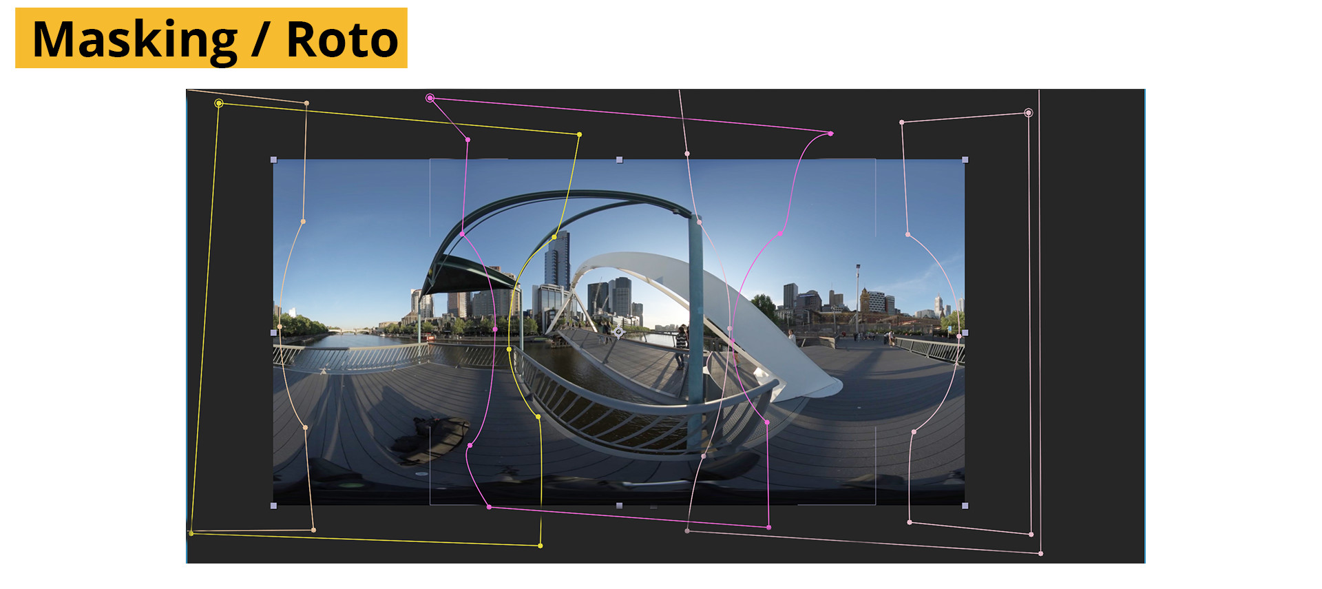
The panorama can now be masked by using roto masks to blend the footage.
Layers can be edited, trimmed and shifted along the timeline to fine tune synchronization.
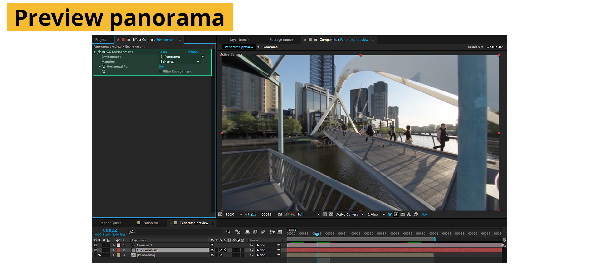
To preview the delivery, create a comp with a camera, assign “CC Environment” to a new solid. CC Environment creates a sphere infinitely far away around the scene, usually used for sky replacements but quite useful for quality checking our Panoramic video. Add the panorama and select it as the source for the environment. Now the scene viewed from the camera, will closely resemble the final delivery. You can change the camera’s focal length to experiment with different views of the scene.
Effects and grading works very differently in VR, so if you want to do further post-production – read the next chapter.
Manual Stitching: The Foundry Nuke
The Foundry’s nuke has a fully fledged 3D environment and a ton of tools that are already geared to working with high dynamic range and lat-long imagery. So the process of stitching can be accomplished in a number of ways. The Foundry has also announced a new toolset being developed specifically for VR, but it is still under development.
The method for After Effects as described above can very easily be adapted to Nuke using the STMap node. An example script can be downloaded at the end of the chapter.
Shooting with Fisheye Lenses
Fisheyes have a long history in VFX work and therefore a solid representation in Nuke. In fact there is a preset within the spherical-transform node specifically for 180 degree fisheyes. Even though there is a preset button, does not mean that it will suit your lens, as no two fisheye lenses produce their images in the same way. Every distortion is different, and Nuke’s version of a 180 degree fisheye is no exception. This is however a very simple way to illustrate the basics of a manual workflow, and we’ll get around the problem of less than perfect undistortion using manual warping.
With that said, this workflow is very similar to the STMap example, with the exception that the shots aren’t aligned for you automatically.
To give the spherical transform node the information it is expecting (A circular image in a 1×1 ratio with a 180 degree field of view), you’ll need to crop the fisheye footage to the correct size. Although the lens produced a circular image, our sensor cropped the top and bottom of the image, this doesn’t affect the expectation of the node though, so our cropping will be a square with black bars along the edges.
Feed the cropped image into a spherical transform and set the output as a latlong and set the output resolution to a 2×1 ratio.
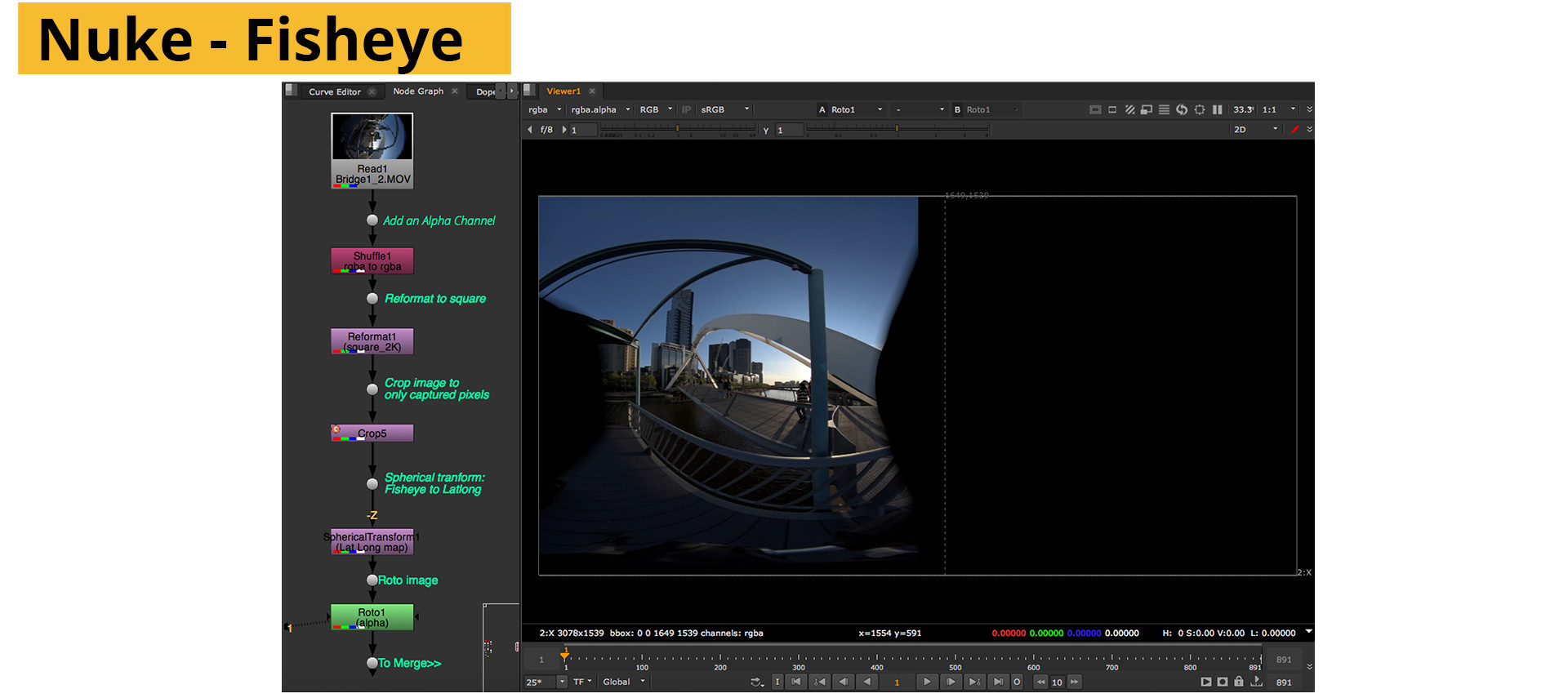
For our example, we’re using 3 shots captured in 120 degree rotations around the Y axis. The camera was vertical. So we’ll need to take this into account in the node. In the source rotation, add 90 under X to right the image and 90Degrees in Y to level the horizon. (The node aligns to the negative Z-axis be default.)
Doing the same with the other 2 pieces of footage, cropping and feeding into a spherical transform. Offset each one with an additional 120 degree rotation and merge the resulting images.
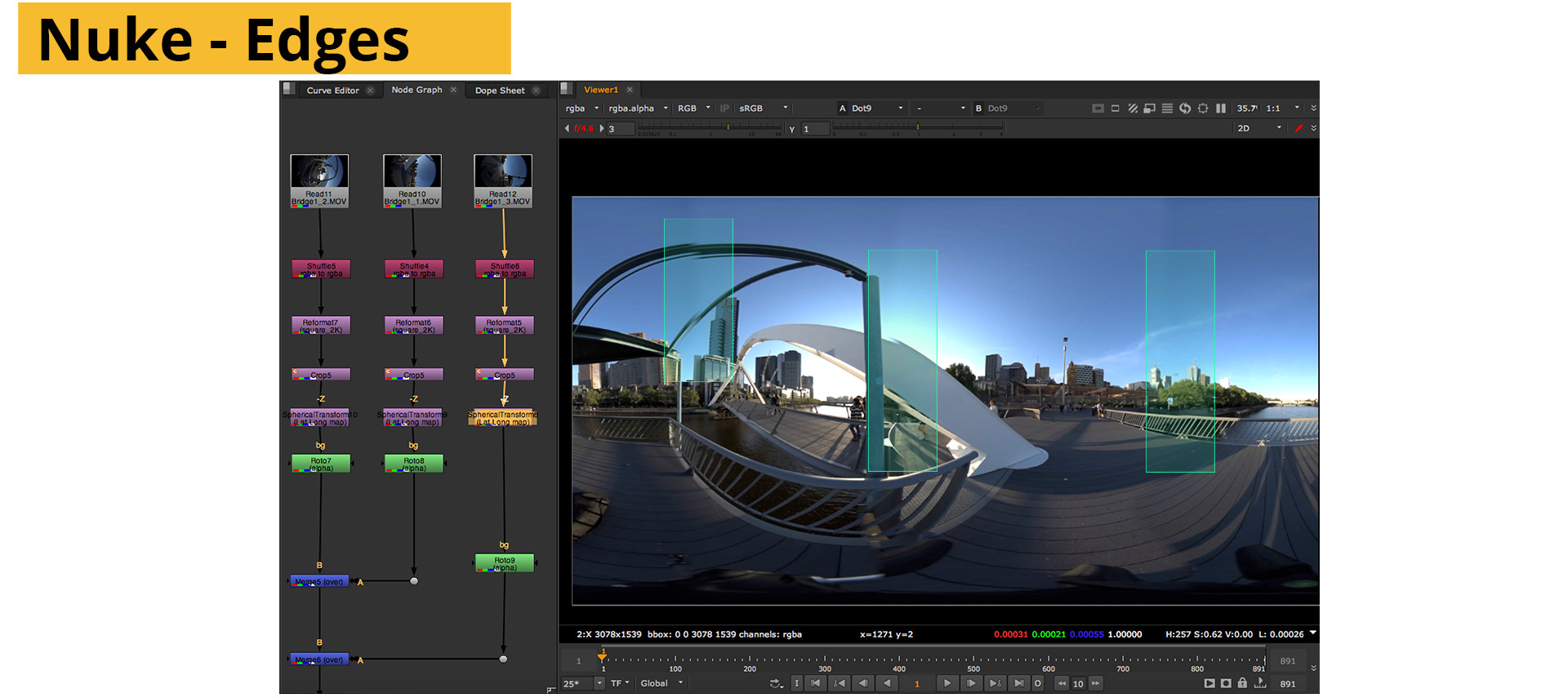
Use feathered roto masks to more clearly define the overlap. You’ll notice lots of parallax style ghosting and artifacts, even though the footage was captured using a nodal head. This is due to the undistortion from the spherical transform node not matching our lens. A full explanation of correctly solving the distortion of a fisheye lens is outside of the scope of this example.
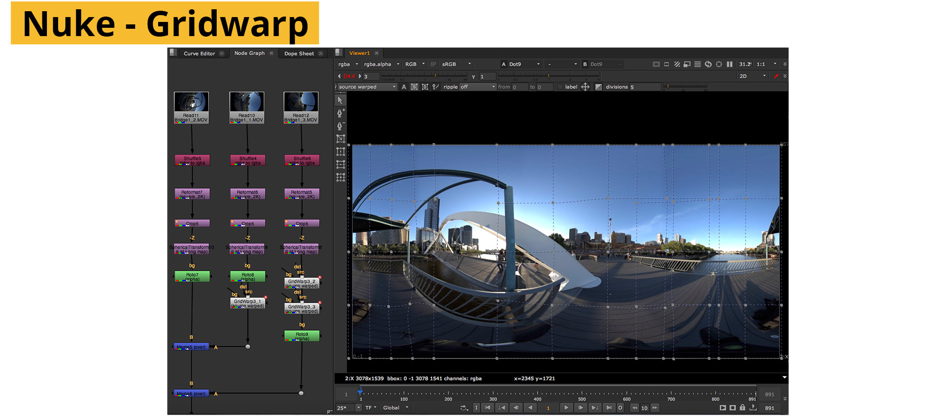
To fix the ghosting, use gridwarp nodes to nudge the edges into alignment. Warping the edges will also form the most intensive part of the process when dealing with footage that has parallax errors.
Manual Stitching:
The Foundry Nuke / Using Projections (Shooting with Normal Lenses)
When fisheyes aren’t being used, as with gopro rigs or any other normal lens, aligning the footage becomes more complicated. Fortunately, finding the distortion becomes less so. For this workflow, we’ll recreate the camera rig within nuke using virtual cameras. From this virtual rig, we’ll project the footage out onto a sphere. The projections will be rendered from a new spherical camera, and thus give us a latlong. There are a number of different ways of approaching this method as well, with many people creating the actual stitch at different points in the script. The advantage to postponing the stitch is that control over combining shots is kept as long as possible, as it becomes increasingly complex to solve stitching errors once the panorama has been created.
In my opinion this workflow can be cumbersome when compared to the STMap/UV workflow from PTGui. Due to the number of sampling nodes (transforms, distortions and scanlinerenders) detail and sharpness can easily be sacrificed leading to soft panoramas. It is however the most logical approach to stitching as the process is very transparent and the process can be visually interpreted and so is a great way to learn. As Nuke continues to be updated, this situation may very well change as the tools become more geared towards 360-content.
The most important part is to know, very precisely, what the original rig was. This means measuring each camera’s dimensions and knowing where the image plane is. This can be a very time consuming and inaccurate process, which may lead to a LOT of trial and error inside nuke. To automate the process somewhat, Agisoft’s Photoscan recently updated their software to include panoramic solving. This allows for the orientation of the capture cameras to be extracted by grouping them together, the cameras can be exported as a Chan file and imported into nuke.
Import your footage and add an alpha channel if not already present. Undistort each piece of footage by using any method you are confident with. As the Undistort will crop to the format by default, adding a reformat node with a larger format and setting scaling set to none in front of the lens distortion node will keep the edges intact.
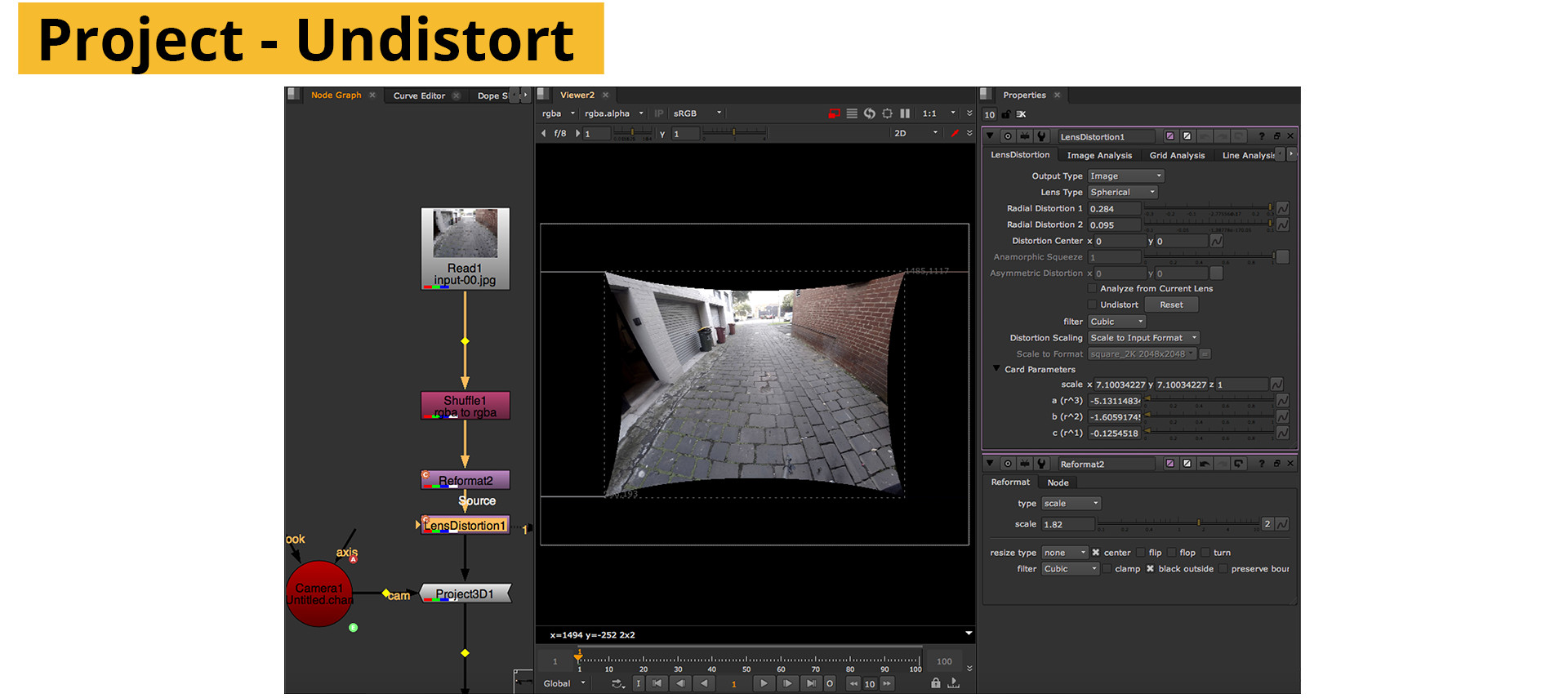
Create a camera node and set its focal length and aperture values to that of your original camera. In the transform attributes set the rotations to match the rig first, it’s easier to see whether your rig calculation is correct when all the cameras are at least pointing in the same direction.
Create a sphere, large enough to see what’s going on, but the radius has no impact on the stitch. Connect each piece of footage to it’s own project3d, along with a mergeMat node. Combine the materials and connect to them to the sphere.
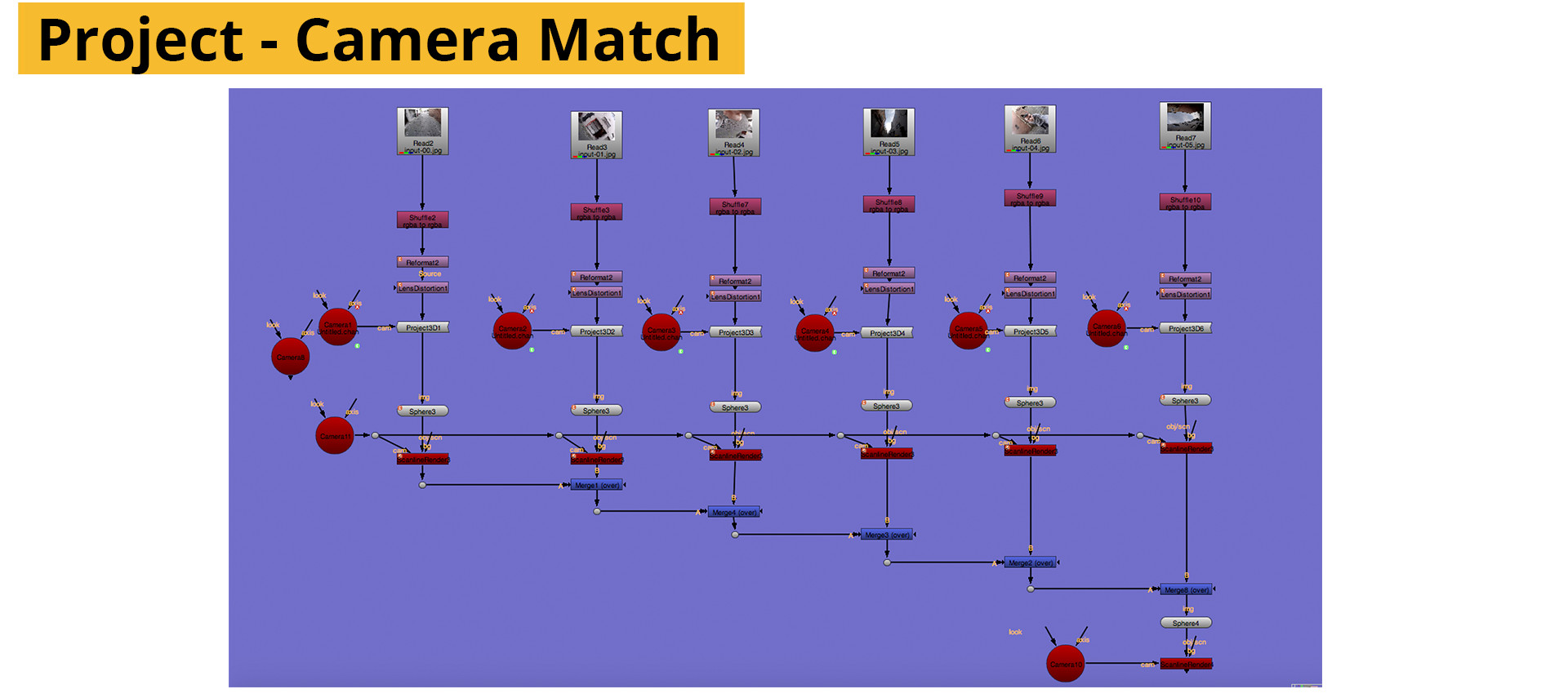
Lastly, create another camera and a scanline renderer. Set the scanline from perspective to spherical. To get the correct projection, create a reformat node set to a 2×1 ratio and connect it to the bg of the scanline renderer.
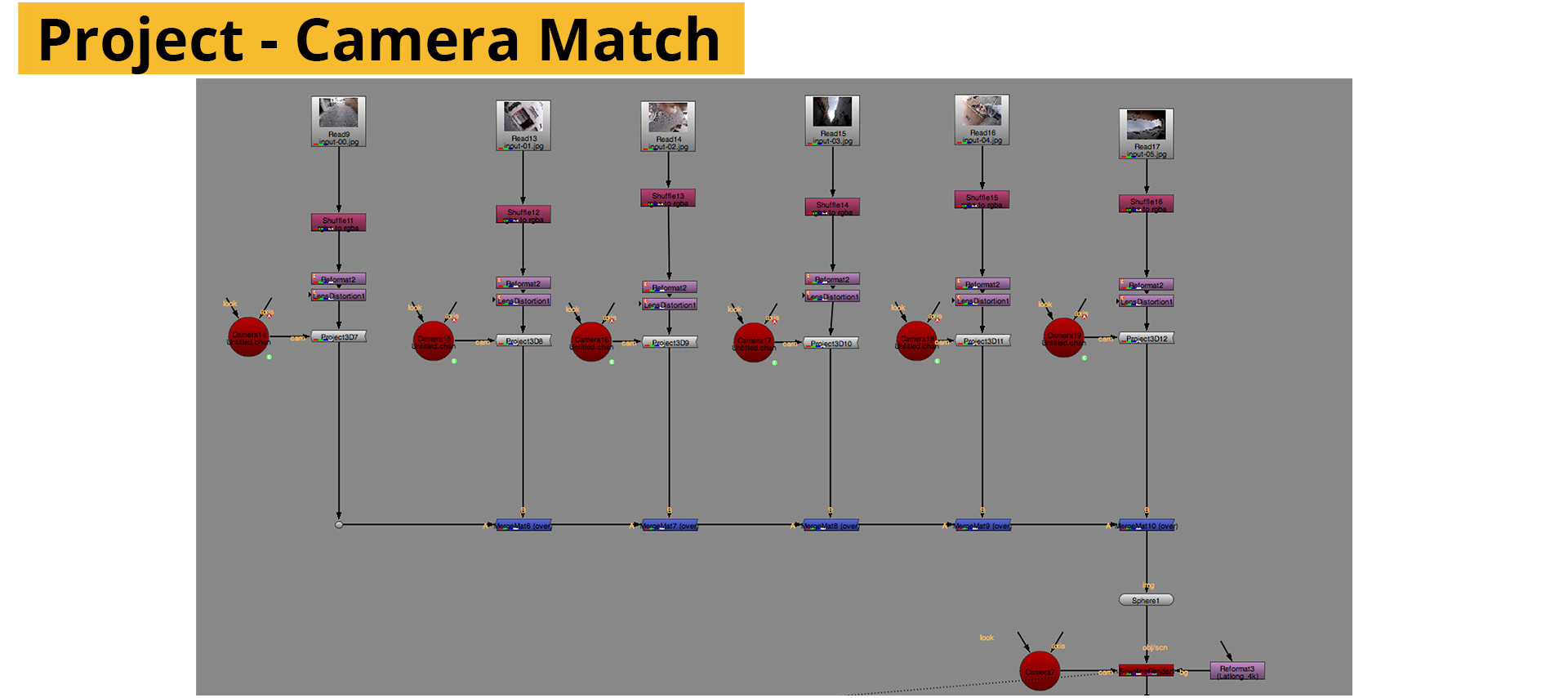
Alternatively, you can set up each image as it’s own scanline render and merge the resulting files together with a normal “over” operation. The net result is the same but some people may find the latter easier to work with as you end up with the different views as portions of a full latlong – making it easier to individually warp and grade.
From here the rig can be fine-tuned by adjusting the translation values of the cameras to more closely match the offset of the real-world rig. Nuke cameras, as with all virtual cameras have to offset between the film back (sensor) and the lens. To account for this the camera needs to be offset to match their real world counterparts. Nuke works in metric, so 1cm is 1 unit.
Once the images match close enough, the last step is to warp the edges either using a gridwarp or splinewarp node.
As the footage will have suffered some loss in sharpness during the stitching process it may be useful to render the final panoramas with a sharpening filter.
Downloads / Assets
UV Maps
HD_16x9_1080
HD_4x3_1440 (Go Pro)
After Effects Project and footage (Requires RE:Map. Download Demo Here.)
Nuke scripts (Version 9.0v5)
Further Reading
Automated stitching applications
Video Stitch Studio V2
Kolor AutoPano Video
PtGui
Hugin – Free
Microsoft ICE – Free
Compositing applications and Video editors.
The Foundry Nuke
Adobe After Effects
Blackmagic Design Fusion
Tutorials
Ptgui Tutorials
AutoPanoVideo Full Workflow
Getting Started with VideoStitch
Video Stitch Workflow
Practical Synchronisation
Other
Stitching 360 using computer vision
Using UV’s for Real time Stitching
Reddit discussion on Stitching
SITE LINKS
INTRODUCTION CHAPTER 2 / THE BASICS CHAPTER 2 / CAPTURECHAPTER 3 / THE STITCHCHAPTER 4 / POST-PRODUCTIONCHAPTER 5 / DISTRIBUTIONADDENDUM / ADVANCED